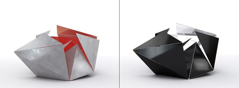
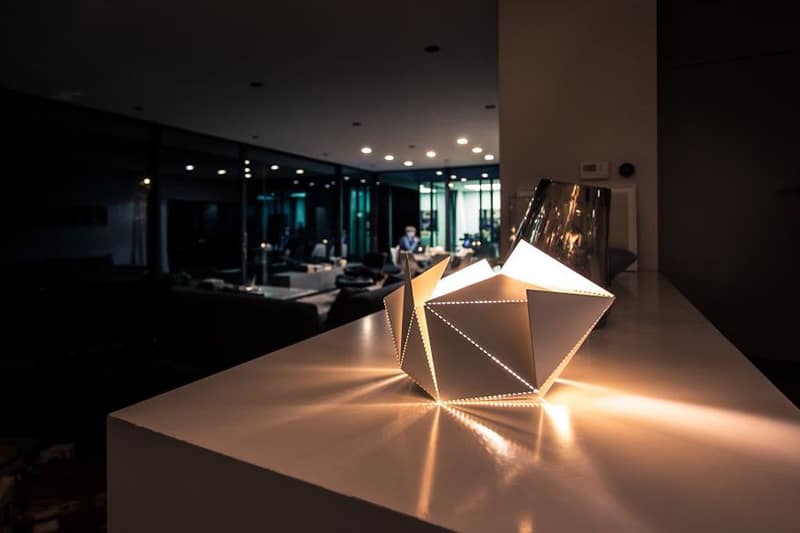
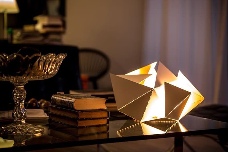
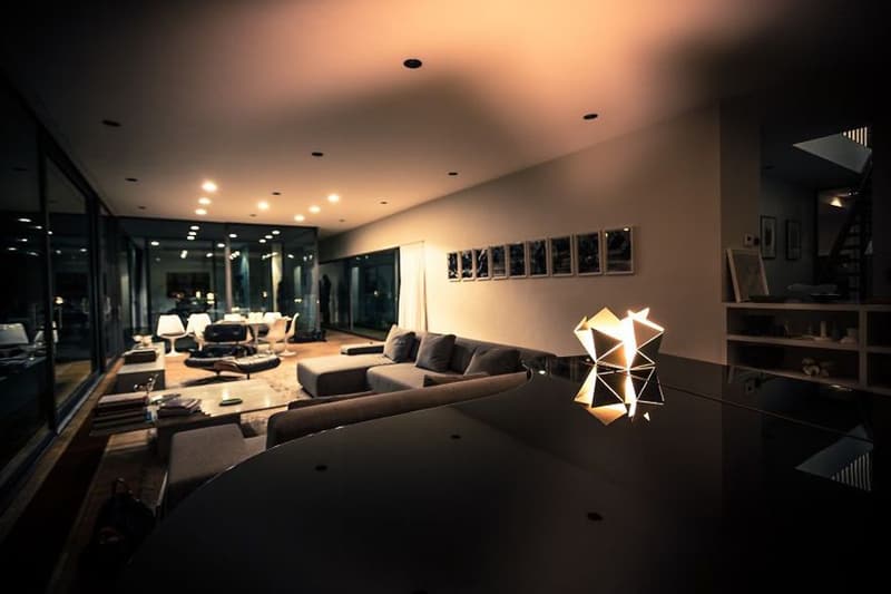
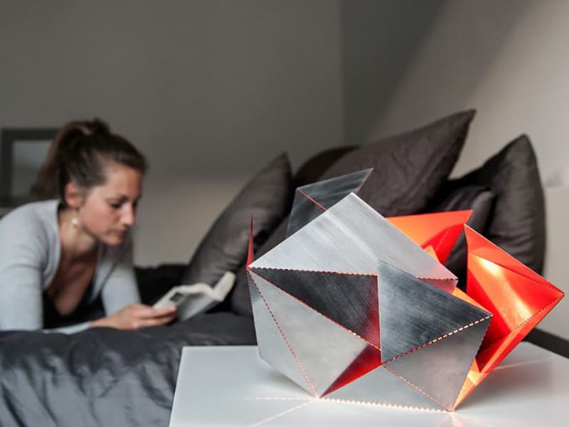
The Folding Lamp by Belgian architect Thomas Hick is an origami light that you can bend and fold into a variety of shapes. The Folding Lamp comes in 5 versions to match your style and your interior. To create the Folding Lamp, you start from a blank sheet of metal that folds along dotted lines, while playing with the order and angle of each fold. You can follow the instructions or let your creative instincts guide you.
Create your amazing design lamp starting from a flat sheet of steel.
Signed by designer, sculpted by you.
According to the architect: “The idea of the folding lamp came when I decided to surprise a close friend of mine who was getting married with a personalized gift. I used to play around with paper and geometrical forms before, so I took the challenge of creating something beautiful from a plain sheet of metal. Due to other priorities, this project was put on hold for a while. One day, seeing my kids play creatively with scissors and paper it got me thinking about this forgotten project and inspired me to re-launch it. My vision is to create a crowdsourcing platform where people can bring their own designs and create their personalized lighting. The role of the platform will be to convert these designs into products by offering manufacturing, marketing and distribution services.”
The available materials and colors are respectively Matt Black & Gold, Matt White & Gold, Matt White & Copper, Sanded Matt White & Red Chilli and Brilliant Black & White Pearl. The lamp includes a 2m power cord to give you maximum flexibility in placing the lamp in your home. The lamps are made in Belgium, Europe and meet European safety standards. They include a touch sensor, a high-end LED filament bulb, EU, US or UK plugs, and works with 110V-240V.
It’s The Biggest Cruise Ship Ever Built… Here’s Some Surprises You’ll Find On board
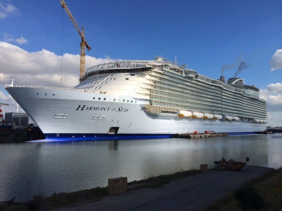
Harmony of the Seas may be the king of the ocean. The biggest ship in the world is the new addition in the Royal Caribbean fleet. Everything about this vessel is done in grand proportions. At 362-meter long, this structure is larger than the Eiffel Tower in France.
It cost a mere $1 billion to build this floating city. It took 32 months to complete the 16 deck ship which boasts the tallest slide at sea, and the deepest pool at sea. Harmony of the Seas set sail this week for the first time from Southampton, England.
Harmony of the Seas can carry up to 7,000 passengers.
Royal Caribbean
23 pools, 20 restaurants, a theatre, casino, hospital, and jail are just some of the amenities found in the ship.
Royal Caribbean
The cruise has seven neighbourhoods like the Royal Promenade, Central Park, and Boardwalk.
Royal Caribbean
Cabins with no windows come with virtual ones from a real time camera from the ship.
Royal Caribbean
The world’s tallest sea slide, the Ultimate Abyss is 10 stories of adrenalin rush.
Royal Caribbean
Daredevils begin their ride in the Ultimate Abyss by entering through a purple anglerfish.
Royal Caribbean
Boardwalk takes you to a retro carousel and arcade area.
Royal Caribbean
The fastest high speed internet is provided on the Harmony of the Seas.
Royal Caribbean
“Harmony of the Seas is the product of our zealous spirit of continuous improvement, where we have combined revolutionary ship design with the technological strides,” says Richard Fain, Chairman and CEO of Royal Caribbean Cruises.
Royal Caribbean
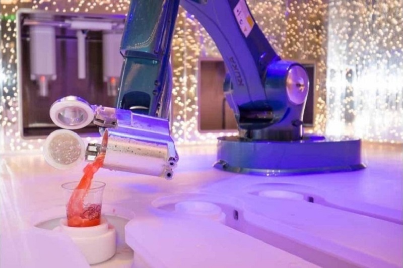
The Bionic Bar employs robot bartenders.
Royal Caribbean
The robotic arms will make your drink exactly how you want it.
Royal Caribbean
The robots can make two drinks per minute and 1,000 drinks a day.
Royal Caribbean
Guests can enjoy the ship’s two FlowRider® surf simulators.
Royal Caribbean
There are two climbing walls, at an impressive 43 feet high each.
Royal Caribbean
The trio water slides Typhoon, Cyclone and Supercell make the Perfect Storm.
Royal Caribbean
The waterpark features water cannons, slides, and waterfalls.
Royal Caribbean
Central Park has over 12,000 trees and plants.
Royal Caribbean
A zip line that flies up to 120 feet above ground will make you lose your fear of heights.
Royal Caribbean
An ice skating rink and a basketball court are just some of the sport facilities available.
Royal Caribbean
Prices start at $1,125 per person.
Royal Caribbean
Harmony of the Seas will spend the summer travelling around Europe before beginning its voyage to the US in the winter.
Royal Caribbean
Like what you’re reading? Subscribe to our top stories.
Quick Tip: How to Setup Units & Use the Tape Tool in 3D Studio Max
In this quick tip, Alex Martin introduces you to two features of 3D Studio Max that many new artists overlook, a correct unit setup and the ever handy tape tool. Working with a correct scene scale is extremely important, especially when it comes to multiple artists working on the same scene, or when recreating accurate lighting for a project. This quick tip will give you a few tips for setting up your units system correctly, and provide a practical example for measuring the distance between objects using the tape tool and how this applies when working with Z-Depth.
1. Unit Setup
Step 1
Whenever we create a primitive object in 3ds Max, it shows its dimensions without any proper unit by default. For example, I have created a box in the viewport and you can see there is no unit setup defined for its dimensions (Length, Width and Height). However these dimensions have some values, but we don’t know what exactly these are; meter, feet, inches, centimeters or something else?
The majority of 3ds Max users just start working this way, and this is indeed a fatal tendency. If you’re working on an architecture or industrial project, or anything which requires a correct unit setup, then you must take care of it.
Step 2
Not working with a correct unit setup can create lots of other problems. Let’s look at it through an example. Say, there are two users A and B, working in 3ds max on two different machines and both are working without setting up the correct unit order. User A has created a biped (scene 1) and user B has made a car (scene 2).
Now, after merging both projects together (scene 3), it shows the real problem. In scene 3, you can see the ratio mismatch clearly. The biped is too big for the car. This happened, because both users were working without setting up the correct unit order. If they had used the unit setup before, this problem could have been avoided.
Step 3
Now, let’s see how to work with the correct unit setup. Open 3ds Max and first of all go to the Customizemenu. Here click on the Units Setup… option.
This opens Units Setup window. Here click on the System Unit Setup button to open the System Unit Setup window. By default, it shows 1 unit = 1 inch.
This means if you draw a box in the viewport, its dimension values are in inches by default. So in this example, a Length value of 40.0 means 40 inches and so on.
Step 4
Now let’s go back to the Units Setup window. You can choose here a metric unit system also. Just turn on the Metric radio button and select any of the available units (meters, centimeters, kilometers etc). Then click on the OK button.
Now create a new Box in the viewport, and you’ll see its dimension values are in meters now.
You can change the unit system to US standard also. You can see I have changed the system unit to Feet/ Inches and now the same box’s dimension values are displaying in feet/ inches. So this is the way to get a correct measurement in 3ds Max.
Step 5
Now let’s see how we can use unit setup in a different case. I have created a biped in the viewport. The question is, how to determine the exact height of the biped? Since the biped doesn’t have any dimension values, we need to apply a trick to know the height of the biped.
There is a simple trick to set the proper height of the biped. Create a Box of the same height beside the biped. Now check the height value of the box. It shows 16 feet and 5 inches. This means the biped has the same height as well. So this is the trick to determine and setup the proper height of a biped.
2. Using the Tape Tool
Step 1
Now let’s see how to determine the proper distance between two objects in 3ds Max. I have created two objects in the viewport, and now we have to get the exact distance between the two.
To know the distance between objects, we’ll use Tape tool. Click on the Helper icon and then select theTape tool.
Step 2
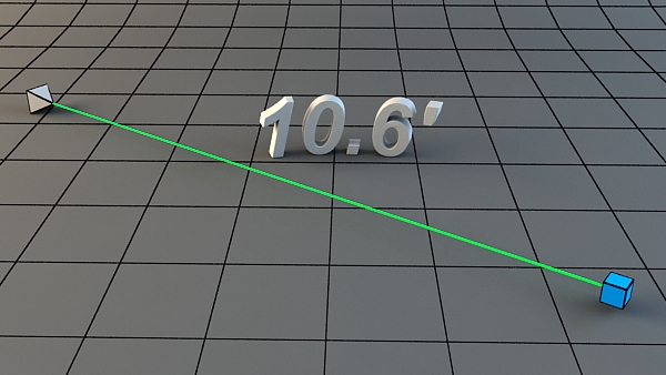
With the Tape tool selected, first click on the starting point, don’t release the mouse button and then click on the end point. The starting point of the tape tool is called the head/ tape and the end point is called the tail/ target. The connecting line in green between the head and tail represents the current distance.
Step 3
If you select the head of the Tape tool, you can see the exact length or distance between the head and tail points.
Step 4
If you turn on the Specify Length option, you’ll see the Length value gets changed and the green line of the tape tool exceeds a bit.
Step 5
You can easily set it correctly by the spinner for the Length parameter.
Step 6
Let’s see through an example, how the tape tool helps in Z-Depth channel extraction. Press the F10 key on the keyboard to open the Render Setup window. Here go to the Render Elements tab and click on Add. This opens the Render Elements sub-window. Here select Z Depth and then click on OK.
Step 7
Inside the Z Depth Element Parameters, there are two options, Z Min and Z Max. If you want the correct Z Depth value, then you must know the correct Z Min and Z Max values, which are actually the distances from the camera focus to the target objects.
Conclusion
So you can see how important the measuring tools are in 3ds Max. I hope you have enjoyed this quick tip tutorial.
Create A 3D Floor Plan Model From An Architectural Schematic In Blender
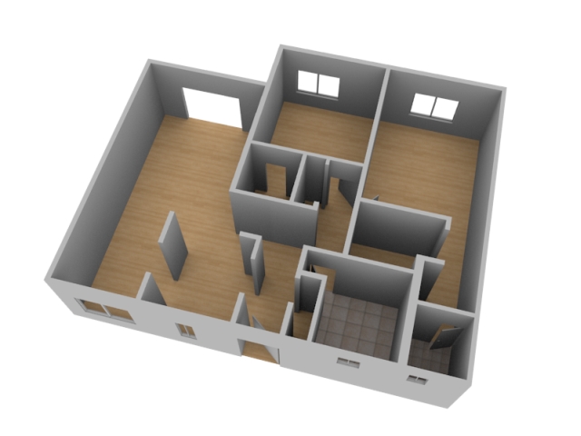
In this tutorial you’ll learn how to create a 3D floor plan model from an 2D architectural drawing. Karan Shah will show you some simple, yet effective techniques for constructing the walls, windows and doors following a basic interior schematic in Blender. With the model complete we’ll add materials and textures, and do a final render of the scene.
Step 1
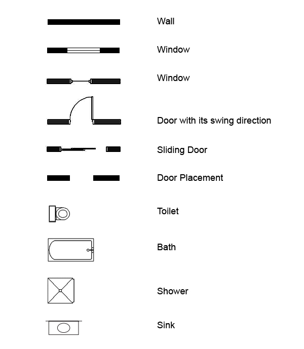
Floor Plans are simply a drawing or a diagram showing a top view of a site layout. You can see the picture to understand the meaning of some basic symbols used. More can be found
here (pdf).
Step 2
In a new file, select all objects with the ‘A’ key and press ‘Del’ to delete them. Press ‘N’ to bring up our View properties. In the Background Image Panel, add your reference image. Here I have used image courtesy ofLiamKeiranCooper Ltd who kept the picture in public domain.
Step 3
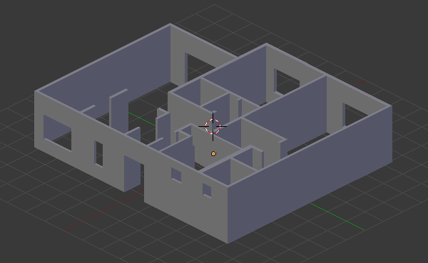
Press ‘7’ on the NumPad to get into the Top view. Here you can see the background image. The view must be set to ‘orthographic’ in order to see the image. You can toggle between the ortho and perspective views with the ‘5’ key on the Numpad. Press Shift+A and add a Plane.
Step 4
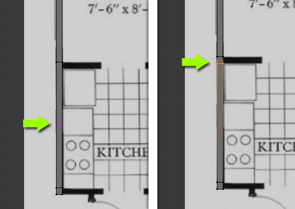
With the Plane selected, press ‘TAB’ to get into ‘Edit’ mode. Select all the vertices with the ‘A’ key, or press ‘B’ to drag select them. Press ‘G’ and move them to the top left corner. You toggle the viewport shading between solid and wireframe with ‘Z’ key. Press ‘S’ and move the mouse to scale them down to fit the width of the wall (as shown below.)
Step 5
Now we will cover all the black solid areas i.e. the walls. This will include the windows as they are part of the walls and will be added later. Any type of door whether it’s a slider or normal, is to be left out. Select the bottom two vertices (press ‘B’ to drag select or Hold ‘Shift’ and Right click for multiple select.) And move them down just before the wall turns left. Press ‘E’ and extrude the wall again until you reach the edge.
Step 6
Select the right two vertices and press ‘E’ to extrude, and match the reference.
Step 7
Now, in order to extrude out a face from the middle, we need to add an Edge Loop. Hover your mouse over the face, and press ‘CTRL+R’ and Left Click to confirm. Move the mouse up and down and then Left click again to confirm its position.
Step 8
Create another edge loop just below the previous one using the same method, matching the width of the wall to be extruded.
Step 9
Select the two vertices and extrude the wall.
Step 10
Create another edge loop on the corner and extrude the right edge.
Step 11
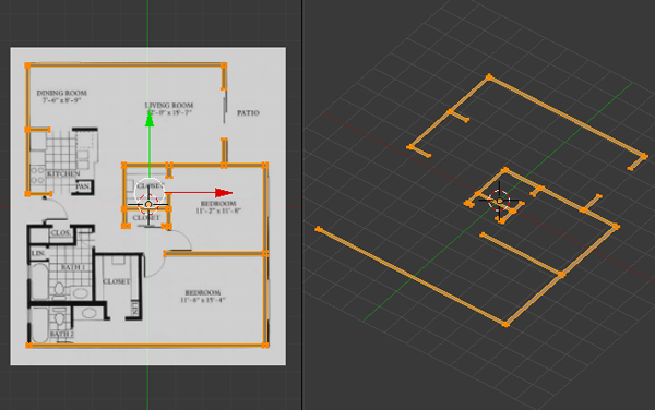
Using the techniques above (extrude and edge loop division) fill all the solid black lines of the reference image with the mesh.
Step 12
To start a new separate wall, duplicate the last edge and then start extruding it. Select the last edge and press ‘Shift+D’ to Duplicate it, and left click to confirm. Move it with the Move control widget or press ‘G’ key of the keyboard. And continue extruding the mesh along to match the reference.
Step 13
Complete the walls with the techniques you learned from above steps.
Step 14
After completing the wall, select all the vertices and then press ‘E’ to extrude them along the Z axis. Now we see that the structure is taking shape. The height should be equivalent to a door.
Step 15
Press ‘Ctrl+TAB’ and select ‘Edge’ in the mesh select mode menu. Select the top two corner edges of a door (hold shift + right click to multiple select) and press ‘F’ to make a Face between them. Do this for all doors. Refer to your image and always check from all views.
Step 16
Press ‘3’ on the Numpad to get into side view, and Press ‘Z’ to get into wireframe view so that we can see all the vertices behind are visible and can be selected. Press ‘B’ to drag select all the top vertices or edges, then Press ‘E’ to extrude them. This will reach the final height of the wall.
Step 17
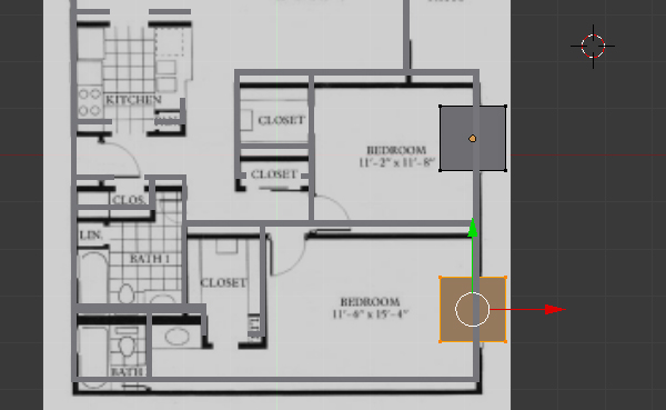
Now we will place the windows. Press ‘TAB’ to get out of the Edit mode, and in object mode, press ‘Shift+A’ and add a ‘Cube’. In the Top view, size (press ‘S’ to scale) and place it where the window is on the reference image.
In the side view, the top part of window should align to the top of door. Press ‘TAB’ to enter into the edit mode to adjust the vertices. Adjust the bottom height of the window too. The width of the cube should be such that it should be half inside and half outside. See image below.
Step 18
Select the Wall mesh with Right click, and in the Properties button window, click on ‘Object Modifiers’.
Click on ‘Add Modifiers’ and select ‘Boolean’.
Step 19
In the Boolean modifiers panel, select ‘Cube’ in the Object, and ‘Difference’ under ‘Operation’.
To see the effect – Select the cube and press ‘H’ to hide it. You will see that there is a “hole” in the wall the size and shape of the cube. Press ‘Alt+H’ to ‘Unhide’ the Cube.
Step 20
Now select the Cube (window) and in the ‘Edit’ mode, select all the vertices and press ‘Shift+D’ to make a duplicate. Place this new cube in the location of the next window.
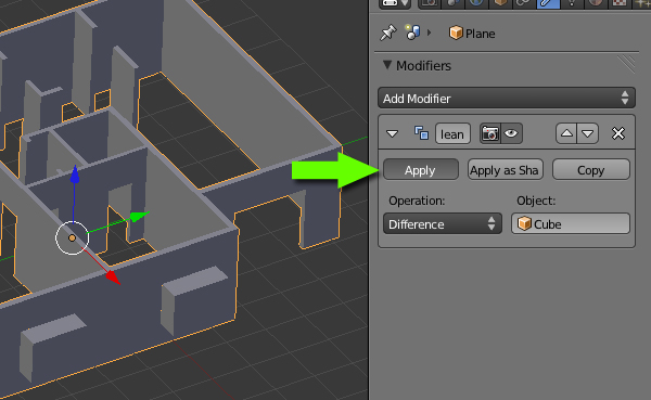
Now press ‘Tab’ to get out of ‘Edit’ mode, and select the Wall mesh and press ‘Apply’ in the ‘Boolean’ Modifier panel. The holes are now part of the geometry.
Move the Cube to see the windows.
Step 21
Similarly create all the needed windows with this Boolean modifier. Try doing them one by one, adjust the size and position of the cube according to the specific window.
Step 22
Now we will create the Floor. In ‘Object’ mode and in the Top view, press ‘Shift+A’ and add a ‘Plane’. Press ‘Tab’ to get into ‘Edit’ mode and adjust the vertices accordingly so that it covers the walls. Create Edge Loops or Extrude the edges where necessary.
Step 23
Make sure that there are no gaps between the edges of the floor and walls. Also in the Side view, move the floor down so it’s aligned with the bottom of the walls.
Step 24
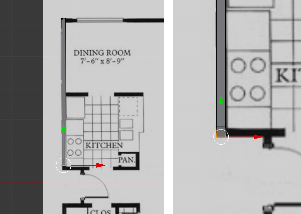
To make doors, add a new’Cube’. And in ‘Edit’ mode, press / on the Numpad for Local view (this will show only the selected object.) In the Top view, Move or Scale the vertices to give it a nice shape. Refer to the image for the height and width.
In the Top view, and in ‘Edit’ mode. Move all the vertices of the door along the Y axis, so that the center point of the object (orange dot) should be at the corner (see image.) This will set the transform orientation of the object from that corner. Press ‘TAB’ to get out of edit mode and then press’R’ to Rotate and see the difference.
Step 25
While in the edit mode, add a new ‘Cylinder’. Rotate and scale it down to create the doorknob (you can add more details if you like.) Press ‘TAB’ to get out of edit mode.
Step 26
With the help of the reference image, place the doors in the correct positions (press ‘Shift+D’ to make duplicates.)
Step 27
Now we will create the window frame. Start with another new ‘Cube’, and press ‘TAB’ to enter into ‘Edit’ mode. Press the ‘Z’ key to toggle wireframe view, so that we can select the back vertices too. Press ‘3’ on the Numpad to get into side view and then extrude the faces as shown in the image to make the window frame. Press ‘TAB’ to exit out of edit mode, and press / on the numpad again to get back to the scene.
Step 28
Scale and place the window frames on the walls. Make duplicates and place them according to the image.
Step 29
Now we will add a texture to the floor. Right Click on the Floor object to select it. And in the Properties window, click on the ‘Materials’ Icon. Add a New material and name it ‘Floor’, increase the ‘Diffuse’ intensity and reduce the ‘Specular’ intensity.
Step 30
Next we will add an image to the floor. (I got mine from Here.) Click on the ‘Texture’ icon next to the Material icon, and then Click on the ‘New’ button. Select ‘Image or Movie’ for the Type and in the Image panel, click on “Open’ and browse for the image.
Step 31
You can preview the texture in the 3d View. Press ‘N’ to bring up the ‘View Properties’ and in the ‘Display’ panel, select GLSL in the ‘Shading” menu (you’ll need to add some lights in the 3d view to see the texture.) Now press ‘N’ again to hide the view properties panel.
Back to the Image Texture properties, scroll down to the Mapping Panel and increase the Size of X and Y to5 or 6 depending upon your image file.
Step 32
Now to add a separate floor to the Bathrooms, we will add a new ‘Plane’ and adjust it’s dimensions and place it just above the wooden floor so that it’s hidden.
Apply an image, just like we did on the floor (I got mine from Here.) Duplicate the Plane and adjust it’s geometry by scaling and extruding for the second bathroom.
Step 33
Select the walls and add a New material to them. Choose any color and Increase the ‘Diffuse’ intensity and set the ‘Specular’ to 0.0
Similarly assign the materials to the windows and doors. You can assign the same material to any object by selecting the material from the list.
Step 34
Now we will prepare the scene for rendering. Make sure you are Not in ‘Edit’ mode (press ‘TAB’ to toggle Edit mode on/off.) Press ‘7’ on the Numpad to get into the Top view, then press ‘Shift+A’ to add a camera.
Rotate and place it however you like. Press ‘0’ on the Numpad to get into camera view.
Step 35
Click on the ‘World’ settings and change the ‘Horizon Colour’ to white, then turn on ‘Ambient Occlusion’ and in the ‘Gather’ panel, increase the samples to 16. In the 3D view delete any lights if they exists.
Step 36
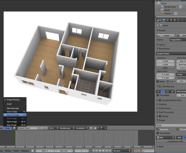
Click on the ‘Render Settings’ button in the property window, and change the Dimensions (resolution) to your desired size. Down in the ‘Output’ panel, choose the file format for your render.
Press ‘F12’ or click on the ‘Image’ button in the render panel. Press ‘F3’ or click on ‘Image > Save image as‘ to save the image.
Here I will show you some of the basic concepts that many students of Max might overlook because they are focused on modelling characters right off the bat. While this is fine, it also makes for a frustrating experience when someone new to Max wishes to unleash their creativity.Therefore this is my main focus here, to help you understand some of the basic things you should have under your belt concerning using this programme in order to free the artist within you!What we are going to start with is learning how to use our Primitives to enable us to quickly get modelling. This is a powerful way to not only create or model quickly, but it can also be a great way of getting some ideas down in 3D space. Remember the point here is to unleash your creativity!The first thing that we must have in our minds is what we are going to model. However, sometimes just letting yourself go is a great way to explore your own creativity. But for this project I am going to begin thinking that we are going to try and model some kind of reactor. This is where I will start, but if we end up somewhere else, it’ll be okay because if our creativity begins leading us down a different path it is best to follow it. Of course, if you are being paid to model something specific then veering off that path will not end well for you. But with this exercise – which is exactly what this is going to be: an exercise – we will not have those constraints.Let’s begin!
1. Open Max, and under the Create tab change the Standard Primitives drop down to Extended Primitives, and then create a Chamfer Cylinder in the centre of the Perspective view. Remember that most of the Extended Primitives have 3 creation parameters that must be created: Radius, Height and Fillet. Here is what it should look with all three parameters created (Fig.01).
Fig. 01
This is the only object we will create. Everything else we do from here on out will be copies of this object. We are also not going to convert it to an Editable Poly because, while it will give us control over the object at the sub-object level, we will lose the power to adjust and manipulate the Chamfer Cylinder primitive. This is important and much overlooked.Â
Just
so we are all on the same page, select this cylinder, go to the Modify tab and make the following settings, shown in Fig.02.
Fig. 02
2. Alright, now using the Move tool, hold down Shift with the LMB (left mouse button) and move the cylinder up on the Z axis a little, then release the mouse. In the window that opens ensure that Copy is the selected method and hit OK (Fig.03).
Fig. 03
Note: from this point on, I am not going to describe in detail how to make these copies, I will assume that you now understand how to do it!
3. Now let’s adjust this new cylinder’s primitive properties, so go to the Modify tab, make these changes and then move the cylinder dow, like so (Fig.04).
Fig. 04
4. Make another copy and move it up (Fig.05).
Fig. 05
5. Copy it, switch to the Front View and then move it down and make these adjustments (Fig.06).
2015 looks like being a bumper year for 3D movies – we look forward to the biggest and best.
When the history of cinema in the 2010s comes to be written, 3D movies are certain to form an important chapter. Once dismissed as a gimmick, stereoscopic 3D has now firmly entered the mainstream.
It’s becoming the norm for cinema tickets to come with a pair of polarized glasses, and increasingly, special versions of films are being made in IMAX 3D too. As this list shows, though, 3D movies still seem to be limited to two genres: action blockbusters and children’s animations. Will 2016 be the year when period drama, European cinema and the indie scene discover the opportunities of stereo 3D, we wonder?
In the meantime, check out our list of this year’s biggest 3D movies and let us know in the comments whether you plan to see them in 2D, 3D or IMAX 3D…
01. Avengers: Age of Ultron
With 2012’s The Avengers making over $1.5 billion worldwide and becoming the third-highest-grossing film in history, a sequel was inevitable, and Avengers: Age of Ultron is one of the most eagerly awaited 3D movies of 2015.
The film will have an astonishing 3,000 visual effects shots, provided by seven to 12 visual effects companies. Obviously this includes Lucasfilm’s Industrial Light & Magic, which opened a facility in London last year to work on the film, which will be released in both 3D and IMAX 3D.
Intriguingly, ILM has developed a new motion capture system for use on Age of Ultron called Muse, which can better capture the actor’s performance and combine different takes. Can’t wait to see what that looks like…
02. Poltergeist 2015
A remake of the 1982 horror classic, Poltergeist 2015 will be directed by Gil Kenan, written by David Lindsay-Abaire and produced by Sam Raimi. While we’re generally against pointless remakes of relatively recent films, Sam Rockwell is always a good turn, and we have to admit that the trailer looks pretty darn cool. Plus at least the addition of stereoscopic 3D brings something new to the table.
03. Terminator Genisys
Will any of the Terminator sequels ever match up to the superlative Terminator 2, the 1991 sci-fi epic with early CGI effects that still put many modern movies to shame?
This, the fifth in the installment, will “reset” the plot and start off a whole new trilogy. Now free from governership duties, Arnie is back in the titular role, with Alan Taylor directing and Legacy Effects responsible for bringing the Terminator endoskeletons back on to the big screen. The trailer looks promising, and the use of Imax 3D should provide a suitably epic experience to the viewer.
But we have to be honest here: it was this very unofficial teaser video, featuring a spoon and a tea cup, that really piqued our interest…
04. Mad Max: Fury Road
More post-apocalyptic unpleasantness comes with the first film in the Mad Max franchise in three decades. Tom Hardy, who played Bane in the last Batman film, takes over from Mel Gibson in the eponymous role, alongside a bald-headed Charlize Theron. The film’s been in developmental hell for over 25 years, with constant start and stops, so here’s hoping it was worth the wait.
But here’s what’s really exciting us. Rather than being retrofitted with stereo 3D as so many modern films are, Mad Max 4 will be shot using 3D rigs and cameras that are being specially developed by director George Miller, according to Inside Film. And that might, just might, be a total gamechanger.
05. Star Wars: The Force Awakens
Yes, the franchise that changed everything is finally back for 2015. Now under the Disney umbrella, a seventh installment in the series will be released this Christmas featuring stars of the 1977 original.
Set 30 years after Return of the Jedi, the film will be released in 2D, 3D and IMAX 3D. Director JJ Abrams has pleased fans with his decision to shoot on film rather than digital, and make greater use of practical effects and rely less on CG than the prequels did. Once again, John Williams will provide the music and ILM the effects.
This may be stating the obvious, but… We. Just. Can’t. Wait.
06. Jurassic World
Twenty-two years after the events of 1993’s Jurassic Park (anyone spot a theme developing in this list?), the dinosaur tourist attraction is finally up and running. But then visitor rates start to decline, so a new attraction is created to re-spark public interest: a genetically modified hybrid dinosaur called Indominus Rex. Not terribly surprisingly, things do not go exactly according to plan…
Colin Trevorrow is directing a screenplay he co-wrote with Derek Connolly, while visual effects supervisor Phil Tippett and Industrial Light and Magic also return to take charge of pixels. With the original movie being such a landmark in CGI moviemaking, it’ll be fascinating to see how much the tech of dinosaur-making has advanced in the intervening years.
07. Minions
While the Steve Carrell-voiced Gru may have been the official star of Despicable Me and Despicable Me 2, it was his small, yellow and somewhat incomprehensible lackeys that kids were queuing round the block to see.
Suitably enough, 2015 sees the lovable Minions get their own feature length adventure, with a voice cast including Sandra Bullock, Michael Keaton, Allison Janney and Steve Coogan. Produced by Illumination Entertainment for Universal Pictures, this promises to be one the summer’s biggest kids movies, and all in glorious stereoscopic 3D.
08. The Hunger Games: Mockingjay Part 2
The Hunger Games quadrilogy reaches its explosive climax this November
Diffcult to believe we know: but already it’s the end of an era, as the final part of the final Hunger Games book plays out on the big screen. All the regular cast return, including the late Philip Seymour Hoffman who’ll appear in fewer scenes than planned now director Francis Lawrence has decided not to use CGI to fill in the blanks.
The only Hunger Games film to get the 3D treatment, this one will be released in 2D, Digital 3D, RealD 3D and IMAX 3D. And with Panem’s revolution against the Capitol turning into full-scale, explosive war, this is one we’d recommend seeing on as big a screen as possible.
09. Fantastic Four
Yes, this one made us do a double-take as well. It’s only been 10 years since the first Fantastic Four film, but apparently Marvel thinks it’s time for another reboot of the franchise already. So here comes an all-new retelling of the story, directed by Josh Trank and starring Miles Teller, Kate Mara, Michael B. Jordan, Jamie Bell, and Toby Kebbell.
Interestingly, Trank has said that the look of the film is heavily influenced by David Cronenberg movies such as 1981’s Scanners and 1986’s The Fly. OTOY,MPC and Weta are handling the visual effects, and a sequel is already in the pipes for 2017.
10. The Good Dinosaur
Dinosaurs will be everywhere in 2015
Disney does ‘alternative history’ in this new 3D kids animation, which asks “What if the cataclysmic asteroid that forever changed life on Earth actually missed the planet completely and giant dinosaurs never became extinct?”
The tale follows Arlo, a 70-foot-tall Apatosaurus with a big heart, who teams up with —a young human boy named Spot. Directed by Peter Sohn, the 3D animation will be produced by Pixar Animation Studios and released by Walt Disney Pictures.
Lance Evans takes you on a day-long crash course of this powerful open source 3D application.
Until the day when desktop holography becomes a reality, 3D will remain the wholly grail of the graphics world. But 3D can be a very technical craft. And each 3D program has its own idiosyncrasies, making it all a bit daunting.
I cut my 3D chops on many programs that are now long dead and forgotten. Blender is one program I’ve wanted to learn for many years. I’ve even downloaded and installed it a few times, but fell short on the follow-through to learn it. Writing this article is my personal impetus to finally get to learning it. Perhaps it can be your impetus as well. Let’s see where we can take this in just 24 hours.
Why choose Blender?
Blender has many qualities that include years of steady development, a prized commodity in either commercial or open source projects. This has netted a broad range of capabilities, beyond even its full range of 3D modeling and animation tools.
For example, Blender has video editing, camera tracking, compositing, and even game creation tools all built right in. The fact that it’s open source and completely free is also an unbeatable perk! (Though donations to the Blender Foundation are a good idea.) With all this power, Blender’s toolset is often directly compared to top programs in the 3D field costing thousands, like Mayaor 3ds Max.
Naysayers may complain it lacks centralized support, since there is no commercial publisher with a help staff. However there is ample support onlineon many sites, and even a real time IRC chat option. This means nights and weekend support too! Plus, the Blender community can be uniquely generous with its help.
The other knock is Blender’s much smaller market share, which means there are perhaps fewer companies looking to hire Blender artists. Having said that, know that this is changing and there are sites like the Blender Network that specialize in matching Blender artists with employers. And even mainstream job sites are getting more Blender savvy every day.
None of this is even an issue if you run your own shop or are just doing your own thing. Then all that matters are the final renderings. And few clients know or care about all this techno-geek talk.
Blender’s own jobs website, and it’s gaining ground on other job boards as well
My first hour with Blender: installing and learning the interface
I went up to Blender’s website , clicked on the ‘Download’ link, and chose between the installers available for Mac, Windows, Linux and even FreeBSD. (And made a small donation while there!) Installation was almost crazy-easy, and fast. Which is common for most open source programs.
Blender splash page
Once installed, I booted it up like a kid on Christmas morning. The splash page had a number of links, including one to the official Blender manual online. The manual is an excellent resource, but perhaps a bit better suited to those that already have an introduction to both 3D and Blender.
Blender’s official online manual
Upon first viewing, Blender’s interface can be overwhelming. But it isn’t as complicated as it first looks. Once you understand the logical thought process it becomes much less daunting. Logic-wise it’s rather similar to Adobe programs like Photoshop or InDesign.
Blender’s default user interface. See the text for a quick explanation of its UI
The default Blender interface is made up of four areas. (A) in the image above is called the Toolbar, a collection of the most commonly used tools. (B) is the 3D Viewport, or work window. (C) is a vertical stacking of many control/preference/properties interfaces, which again, is just like Adobe products you know. (D) is the timeline, for animation work. You might be familiar with this from programs like After Effects.
Understanding these basics makes Blender all the more approachable. Although not necessarily more useable. Before looking at any instructions, I felt compelled to muck about with the buttons, doodads and doohickeys, and hoped to find my way around. But I’ll admit that I wasn’t too successful. I began to realize that Blender wasn’t quite as intuitive – at least for me – as I had hoped.
So I started to explore what alternative ways I could go about learning it, beyond the button-poking. I quickly found out there are quite a few learning options out there.
An extreme example of multi-monitor support
Hours two-four: organizing my education
Starting my second hour with Blender, I began hunting for ways to learn it. I started out the way many of you would, by looking online for books. A quick search turned up dozens of books which included titles such as ‘Blender 3D Cookbook’ and ‘Blender Basics’ (both from PACKT Publishing), and ‘Blender for Dummies’ (John Wiley & Sons), all recently published as print and Kindle editions.
I ordered a few of these books for download. Which books best fit your learning style is up to you. As might be expected by the title, the ‘Dummies’ books take extra pains to make easing into a new subject as painless as possible, so are a good place to start. But they also tend to not go as deep as other offerings. All the books were well written and took me step by step.
And while I began learning from these books, I had to acknowledge that whether it’s our cultural evolution, or just me getting older, I found it harder to read this tech material than I used to. So I began looking for other ways to learn.
Hours four-10: video education, part one
Again, I didn’t do anything different here than most of you, I went trolling around YouTube with search phrases like ‘learn blender’, which gave a return of 157,000 videos. I’m sure most had more to do with making a good smoothie, but still, there were hundreds on Blender 3D.
An advanced subject: creating a city in Blender
Some of the most popular Blender tutorial channels included Blender for Noobswith over 27k subscribers, Blender Guru with over 153k subscribers (see the amazing architecture video!), and tutor4u with over 172k subscribers.
Pure fun: Minions in Blender!
Jacob Lewis offers a 2014 updated 10-part video series called ‘Blender Absolute Beginner Tutorial’ with about 380k subscribers. One video that is seriously worth a look is Max Coulfield’s great Blender sculpture timelapse.
‘Sculpting’ a young female head and shoulders
I spent time finding and then watching many videos, and at this point I had clocked in roughly 10 hours of working on the Blender project, across two or three days. Trying to do it all in one day would surely have exploded my tiny head.
Hours 10-15: video education, part two
After viewing YouTube tutorials for a bit, I will admit to a bias against any that begin with “Yo-yo fellas… wassup?” An experience that can leave you wanting more formally prepared material.
So I finally did something that many of you might not actually do. I contacted Ton Roosendaal, the original creator of Blender, and now the Chairman of the Blender Foundation. He was gracious and we exchanged a number of emails. At his suggestion, I got in touch with Jonathan Williamson, a co-founder and instructor at CG Cookie, an online computer graphics video education resource. CG Cookie has courseware for Blender, as well as other subjects like creative concepting and Unity game development.
CG Cookie offers online video courseware on Blender
CG Cookie offers what they call ‘Learning Flows’ for Blender, which contains 141 separate video installments. These are broken down into 9 sections, with topics like modeling, lighting, etc. The first module in the series is ‘Blender Basics’, which they make available at no cost. It contains six videos that run about a half hour total. Over the next few days I watched the intro videos, and as many of the follow-up sections as I could. All the while popping back to Blender to try things out.
Hour 15 and beyond…
I also touched base with Anja, who runs the Blender Shop on blender.org. She provided a long list of Blender learning resources, which we have reprinted at the end of the article.
So by the time I was nearing my 18th hour with all of this, I was feeling like I was in a fairly good place. By that I mean I could navigate around the interface with aplomb, I could create, modify, and texture map models (with limits on complexity), light them, and render out basic animations. In other words, I could knock out basic day-to-day 3D work. No character modeling, video editing or compositing, I’ll leave that for another day.
If this was for myself instead of an article it would have gone faster. One book and one video series would have been fine. I’m sure you’ll keep things simpler.
So what are you waiting for? Download it now, and let us know how your learning curve goes!
Resources (from Anja at Blender Shop)
A good way to learn Blender if you don’t have experience with 3D
programs is to start with Blender’s own tutorials and manual.
You can find lots of free tutorials on the internet about learning Blender.
Here are some links with lots of information:
http://wiki.blender.org/index.php/Doc:2.6/Tutorials
Want to start a VR project but don’t know where to start? Then this is the guide for you!
Download this free guide to VR today
Even though virtual reality is a big trend, not everyone knows how to do it. To help out, Chaos Group Labs just released a free VR Guide for artists and hobbyists who want to start a VR project, but don’t know where to begin.
Common pitfalls associated with VR are addressed through scientific research and production insights, culminating in step-by-step instructions that explain how to make VR stills and video.
What are the differences between the current headsets?
Where should I place my camera to create the best experience?
How do I make sure people don’t get motion sickness?
Is there a correct height or scale that people will respond to best?
There are even sample architectural visualization examples that let people see how you can turn old or new pre-rendered content into a compelling VR experience using V-Ray. We’d urge you to check out the Salle Labrouste room: it’s quite amazing.
Issue 205 of 3D World comes with over 40 hours of free video training to get you started in CG art. Just pick up the issue to download your free content!
Discover how to create an amazing 3D mech in the new issue of 3D World
With a cover tutorial on modelling, texturing and rendering a realistic mech, 3D World issue 205 focuses on hard surfaces and all things mechanical.
The issue gathers together leading CG artists, including Furio Tedeschi, Tor Frick and Paul Massey to discuss how to design, model and render robots and mech using modo, ZBrush, Maya and other leading software.


Tutorials this issue cover getting started in Quixel 2, creating a dynamic dress in Marvelous Designer 5 and modelling foliage for arch-viz using 3ds Max and GrowFX. Plus, Hannah Kang updates Norman Rockwell as she reveals how to add personality to your ZBrush sculpts. All tutorials come with video, resource files and extra content.


Inside issue 205…
Feature: Creating the VFX for The Revenant
Feature: Making a 3D studio in Unity for VR
Artist Q&A: It’s a robot modelling and rendering special
Tutorial: V-Ray for Nuke, master the latest compositing software
Artist Showcase: The best art from the CG community
Reviewed: Poser 11, Redshift and Paint & Stick get tested
Learn from master artists to improve your 3D artExperts share their processes and techniques for creating amazing mechanical marvelsFind out how to model, texture and scatter detailed vegetation for use in architectural imageryDiscover the best digital art from the CG communityArtist Camille Kleinman shares her process for creating a realistic dress in Marvelous Designer 5Discover how to design, model and render a tank-inspired walking mech
The Smithsonian is the world’s largest research and museum complex, with 19 museums and galleries, the National Zoological Park, and various research stations. More than 137 million objects detailing America’s story are housed here, so you’d better prepare for a long week of walking. There’s so much to see that, if you spent one minute day and night looking at each object on exhibit, in ten years you’d see only ten percent of the whole. Therefore, it’s wise to head out with a plan. Focus on only one or two exhibits at two or three different museums.
Main attractions: Dorothy’s ruby red slippers, the dresses of the First Ladies, and the original Star-Spangled Banner at the National Museum of American History; the Gem Hall (including the Hope Diamond) at the National Museum of Natural History; and the Wright brothers’ 1903 Flyer, the Spirit of St. Louis, and the Apollo 11 command module at the National Air and Space Museum.
Le Louvre, Paris, France
The Louvre was a medieval fortress and the palace of the kings of France before becoming a museum two centuries ago. The addition of I. M. Pei’s pyramid shocked many when it was unveiled in 1989 as the new main entrance, yet it somehow works, integrating the palace’s disparate elements. The museum’s collections, which range from antiquity to the first half of the 19th century, are among the most important in the world. A good place to start is the Sully Wing, at the foundations of Philippe-Auguste’s medieval keep—it’s in the heart of the Louvre, kids love it, and it leads straight to the Egyptian rooms.
Main attractions: “Venus de Milo,” “Winged Victory of Samothrace,” and Leonardo da Vinci’s “Mona Lisa.”
The Acropolis Museum, Athens, Greece
The stunning ground floor gallery houses finds from the slopes of the Acropolis. Its amazing transparent glass floor provides a walk over history, with a view of the archaeological excavation, while sloping upward to the Acropolis with sanctuaries of the Athenians from each historic period nearby. Smaller settlements have been excavated, yielding glimpses of Athenian life. For the first time, the exhibits in the Archaic Gallery allow visitors to take in all sides of the objects, which are displayed in open spaces characterized by changing natural light.
Main attractions: The frieze of the Parthenon is mounted on a structure with exactly the same dimensions as the cella of the Parthenon, giving comprehensive viewing of every detail.
State Hermitage, St. Petersburg, Russia
Russia may be isolated from the artistic centers of Paris, Rome, and London, butthe Hermitage has managed to acquire a spectacular collection of world art—more than three million items—spanning the years from the Stone Age to the early 20th century. The museum occupies six buildings along the Neva River, the leading structure being the confection-like Winter Palace. This gloriously baroque, blue-and-white structure was finished in 1764 and over the next several centuries was the main residence of the czars. Catherine the Great founded the museum that same year when she purchased 255 paintings from Berlin. The museum’s focal point is Western European art—120 rooms in four buildings ranging from the Middle Ages to the present day. Rembrandt, Rubens, Tiepolo, Titian, da Vinci, Picasso, Gauguin, Cézanne, van Gogh, and Goya are all represented here. For in-depth tours, contact Glories of the Hermitage.
Main attractions: The Treasure Gallery’s Gold Rooms showcase golden masterpieces from Eurasia, the Black Sea Littoral in antiquity, and the Orient. The museum also houses pieces from Nicholas II’s private collection, including paintings, drawings, and medals created to commemorate his coronation.
The British Museum, London, England
Britain’s largest museum looks after the national collection of archaeology and ethnography—more than eight million objects ranging from prehistoric bones to chunks of Athens’ Parthenon, from whole Assyrian palace rooms to exquisite gold jewels.
Main attractions: The Egyptian gallery boasts the world’s second finest collection of Egyptian antiquities outside Egypt, including the Rosetta Stone, carved in 196 B.C.
The Prado, Madrid, SpainThe Spanish royal family is responsible for the Prado’s bounty of classical masterpieces. Over centuries, kings and queens collected and commissioned art with passion and good taste. In addition to stars of Spanish painting such as Velázquez, Goya, Ribera, and Zurbarán, the Prado has big collections of Italian (including Titian and Raphael) and Flemish artists. Fernando VII opened the collection to the public in 1819, in the same neoclassic building it’s housed in today, designed by Juan de Villanueva.
Main attraction: “The Three Graces” by Rubens.
The Metropolitan Museum of Art, New York City, New YorkThe Metropolitan Museum of Art is the largest museum in the Western Hemisphere. Its collection of more than two million items is not only broad—covering the entire world, from antiquity to the present—but deep, with holdings so large in a number of areas that some might be considered museums unto themselves. Its European paintings are stunning: works by Botticelli, Rembrandt, Vermeer, Degas, Rodin, and other luminaries. The Egyptian Collection showcases the tomb of Perneb (circa 2440 B.C.) and the exquisite Temple of Dendur (circa 23-10 B.C.). The American Wing contains American arts and crafts, including a room from a Frank Lloyd Wright Prairie House. And the list goes on and on.
Main attractions: “Adam and Eve,” the well-known engraving by Albrecht Dürer, is only one of the many impressive pieces you will discover at the Met.
The Vatican Museums, Vatican City, ItalyTwenty-two separate collections comprise the Musei Vaticani, each one more spectacular than the next. The most famous are probably the Museo Pio-Clementino, with its splendid classical sculpture; the Raphael Rooms, entire rooms painted by Raphael; the Pinacoteca (picture gallery), which contains the cream of the Vatican’s collection of medieval and Renaissance paintings; and, of course, Michelangelo’s Sistine Chapel. But there is also the ancient Egyptian exhibits of the Museo Gregoriano Egizio, as well as the Etruscan offerings of the Museo Gregoriano Etrusco. And that’s just a start.
Main attractions: The renowned Sistine Chapel and the Raphael Rooms are not to be missed.
The Uffizi Gallery, Florence, Italy“Great” is an overworked adjective in Italy, where so many of the country’s monuments and works of art command the highest praise. In the case of the Galleria degli Uffizi, it barely does justice to a gallery that holds the world’s finest collection of Renaissance paintings. All the famous names of Italian art are here—not only the Renaissance masters, but also painters from the early medieval, baroque, and Mannerist heydays.
Main attraction: “The Birth of Venus” by Botticelli is one.
Rijksmuseum, Amsterdam, the NetherlandsAbout 900,000 objects fill the Rijksmuseum, the largest collection of art and history in the Netherlands. It is most famous for its paintings by 17th-century Dutch masters, including Ruysdael, Frans Hals, Johannes Vermeer, and Rembrandt van Rijn. Established in 1800 to exhibit the collections of the Dutch stadtholders, the Rijksmuseum also displays art from the Middle Ages. The main building is closed for renovation until 2013; collection highlights are displayed in the Philips Wing and at Rijksmuseum Schiphol.
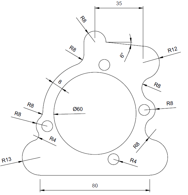
In this session there will be nothing difficult, except the fact that it will help you develop yoursense of analysis while using AutoCAD.
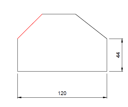
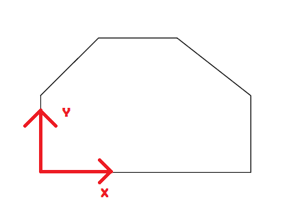
Looking at the exercise below, you should be able to, from a first look, determine all commands you need to be able to accurately replicate the object of today’s experiment.
You by now possess all you need to be able to complete the following without any problem
LEARNING AUTOCAD BASICS
FIGURE 1
FIGURE 2
hey! If you have any confusion about this, Just leave a comment below. Let me know what is confusing about this, I will make it clear for you
EXECUTION
For some, figures above will not be self-explanatory enough, that is why we are bringing the following image. Pay attention to the skeleton-image used while creating the project, you will notice this is even easier that what it seemed at first.
Our suggestion will be to start from the base line (line of 80 units). All information are provided for this not to be a headache.
Feel free to drop a couple of words below in case of difficulties.
We slow down a little today, and we would like you to come back and use some basic commands we think we have not made use of enough.
Now, we are going to look at the CHAMFER command and play with the UCS command a little bit more than we did in the past days.
LEARNING AUTOCAD BASICS
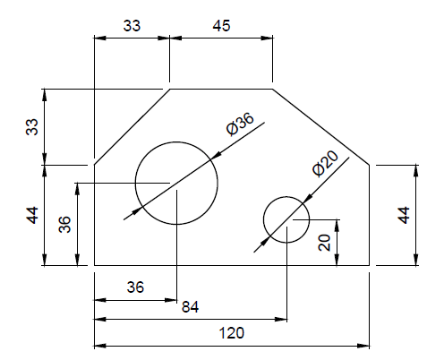
Here is the object we will try replicate in this session, pretty quick one huh!?
We have been into more difficult situation!
EXECUTION
Remember you can do it your own way, but here is how I will suggest you do it.
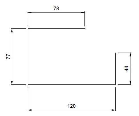
Start with the following. Four lines, you have all dimensions, pretty easy
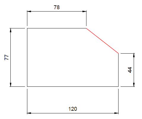
Then, use a line to close the object. You need not to know the length of this line, just use those two points to get it.
Now use the CHAMFER command on the left upper corner. The Chamfer distances are 33 x 33 units.
Learn how to use the CHAMFER command in AutoCAD
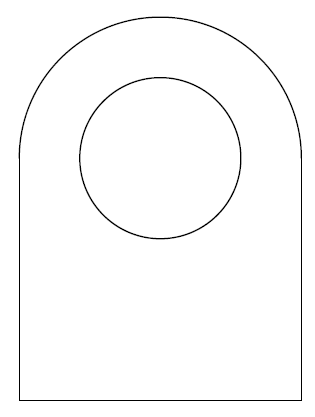
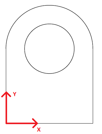
We have made an extensive use of the UCS command earlier. Move the UCS to the position shown on the image below, that will allow you to get the circles we are trying to create at their right positions.
After Getting the UCS at the position shown above, the center of the bigger circle will be at the point of coordinates (36,36) and the center of the small circle will be at the point of coordinates (84,20)
We hope your assessing skill has improved, meaning you are more able to judge the difficulty of an exercise just by looking at it.
In this post, we are going to keep on using basic AutoCAD commands and focus more on how to combine their use to accomplish a specific task.
LEARNING AUTOCAD BASICS
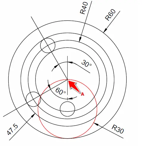
The following are the images we are going to be using today.
FIGURE 1
FIGURE 2
EXECUTION
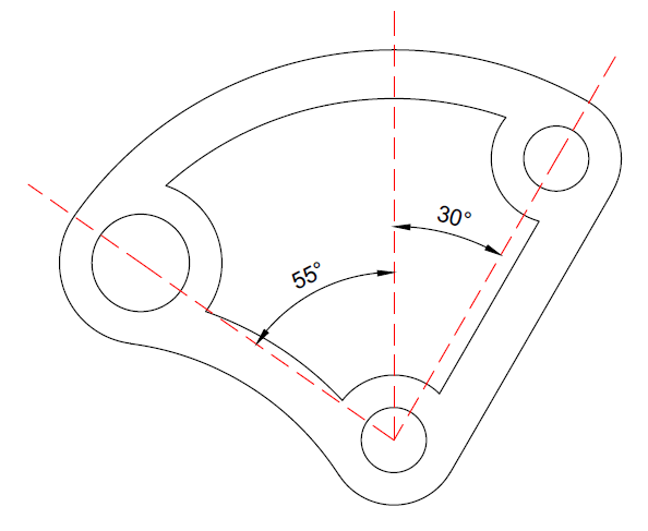
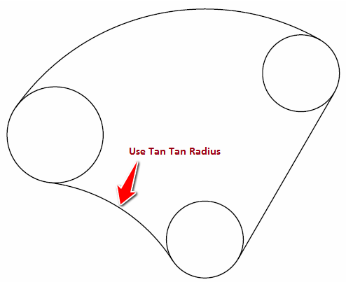
Start by creating the following.
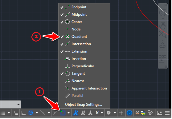
The first object you should create is the red circle. Then make sure the QUADRANT mode is activated in the Object snap settings, this will help you snap the center of those big circles at the point A.
(Right click on 1 and tick 2)
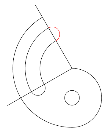
After proper trimming you will end up with the following image
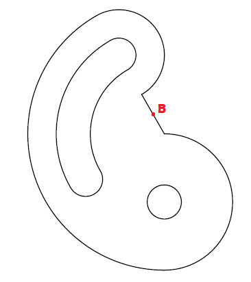
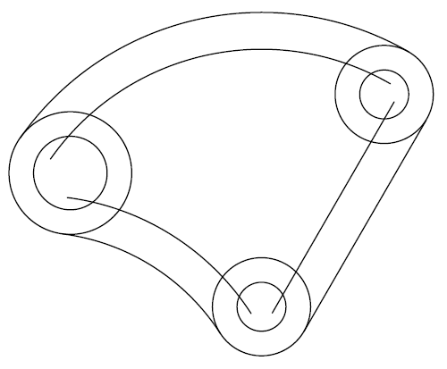
Use the OFFSET command on the red part to obtain the following. OFFSET distance = 12.5 units
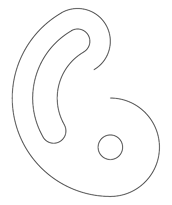
Draw a line from the two openings of the object, and create a circle using the middle point B of the line you have just created.
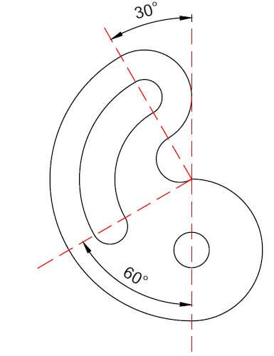
We have not talked about the small circles 30 and 60 degrees away from the vertical. Using techniques we have used to create objects in previous DAYS, those should not be a problem.
The present is one of a kind. It is good to know that the objective is not only to be able to useAutoCAD commands but also to use-your-brain-cells to help combine all these commands to get to the final image.
One thing you should have in mind is that there is more than a way to get to a destination using AutoCAD, just remember to check your dimensions at the end of the exercise and make sure they match ones mentioned on the image-exercise.
We will look a little deeper into the OFFSET command today. It is needed.
OFFSET COMMAND IN AUTOCAD
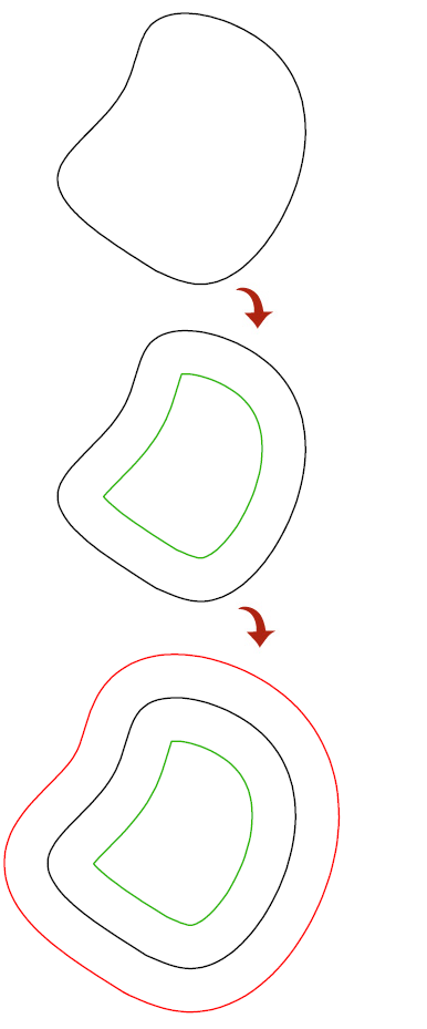
The OFFSET command helps create parallel lines and parallel curves.
If you have a object and want a similar parallel object to it, this command will be helpful.
To use the OFFSET command
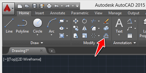
Click on the OFFSET icon
Specify the OFFSET distance and Press Enter
Select object to OFFSET
Specify a point on side to OFFSET
LEARNING AUTOCAD BASICS
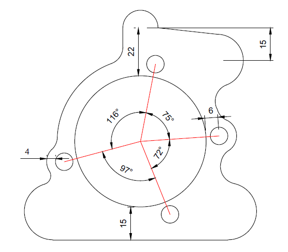
The use of the ROTATE command will be required in this exercise, as well as the OFFSET command.
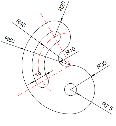
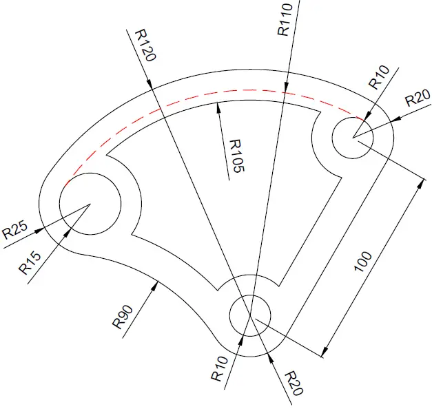
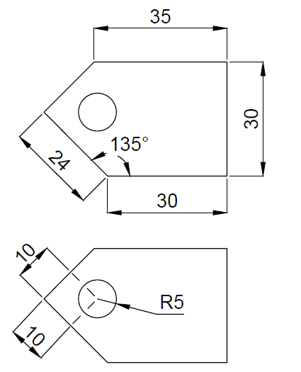
Below you will find diverse dimensions to help the replication of this session’s task.
FIGURE 1
FIGURE 2
EXECUTION
You need to start from the outer part of the object.
After getting the above figure done, OFFSET all circles with 10 units inwards, and OFFSET all line with 15 units inwards.
And you should end up here.
All you need to use the TRIM command and the FILLET command to get all done.
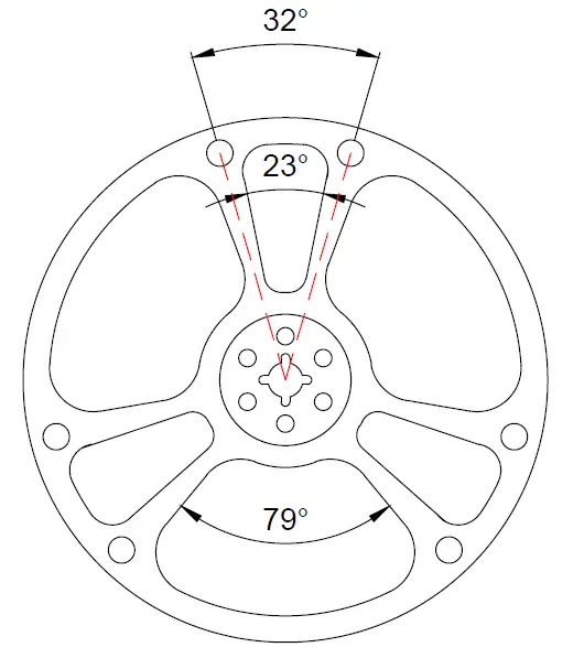
In this session we will be challenging ourselves to learn how to play with the ARRAY command in AutoCAD.
The image below is one of those that may best serve this purpose. It is to be noted that all slots are equally spaced around the circles.
Feel free to visit the post where we practiced and talked about the use of the ARRAY command in AutoCAD.
LEARNING AUTOCAD BASICS
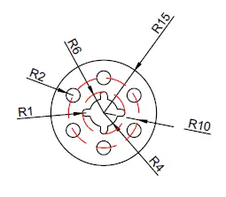
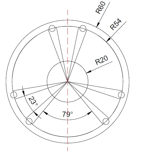
There is not much to be done in this one but the proper use of the ARRAY command. All you will need is to have mastered the TRIM command, the LINE command, the FILLET command and theCIRCLE command.
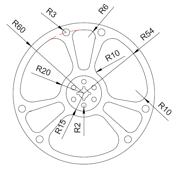
Below we have split annotations in different figures to avoid having a bushy image. Combine all information available on the figures if you want to accurately replicate today’s exercise.
FIGURE 1
FIGURE 2
FIGURE 3
Piece in the center of the exercise.
EXECUTION
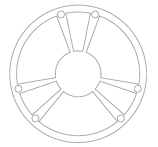
The following image might be helpful to you to have a good start
After proper TRIMMING, you will be left with the following
Now all you need to do is to use the FILLET command to round edges and create objects that are in the center of the figure.
In this post we will be learning how to use the TRIM, CIRCLE command while trying to replicate the image below.
We have, in the last session, learned how to play with the LINE command and use Options of the Status bar. We will keep on playing with those features, adding up to them few others.
LEARNING AUTOCAD BASICS
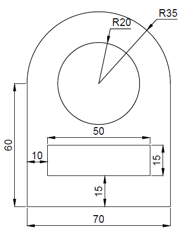
The primary figure that will help easily replicate this exercise is the following.
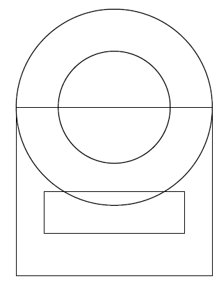
Two circles and two Rectangles.
What is the easiest way to get to this.
Create the big rectangle using the LINE command
Use the Center of the top side of the triangle to create the two circles.
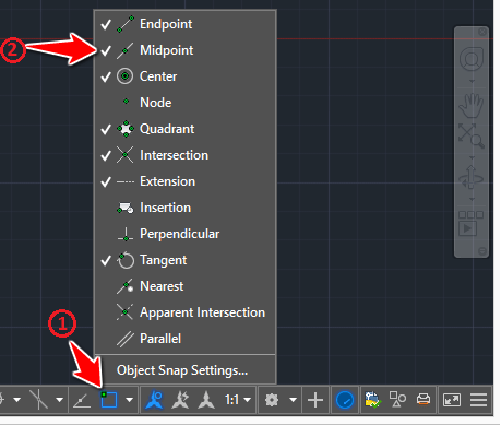
For step 2, you need to turn the Midpoint ON if you want to be able to find the center of that segment while creating the circle
Here is how to do it (right click on 1 and tick 2)
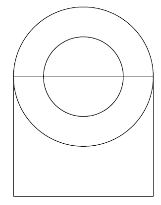
Now you should be at the following point
Trim the big circle and Erase the top side of the rectangle
Now all we need to do is create the small Rectangle. Given dimensions given above, if we consider that the left corner of the figure is at the point of coordinates (0,0), we need to start the small rectangle at the point of coordinates (10,15)
What we will do.
Move the UCS to the left down corner of the figure
Start the line at the point (10,15)
HOW TO MOVE THE UCS TO THE LEFT DOWN CORNER OF THE FIGURE
Type UCS
Select the point
Move the cursor on the x direction and click
Move the cursor on the y direction and click
This is what you are supposed to get
Notice the UCS
Now you can easily start the line at the point (10,15) and create the small rectangle.
Not like the previous DAY, we are going to start learning cool things today. Not to say that DAY 1 was useless, that helped to warm up.
We have lately learn the basic basics in AutoCAD, and you should by now know the environment and I have no doubt that you are familiar with common words used here to describe stuff such as Command window, Status Bar, Navigation bar…
LEARN AUTOCAD BASICS
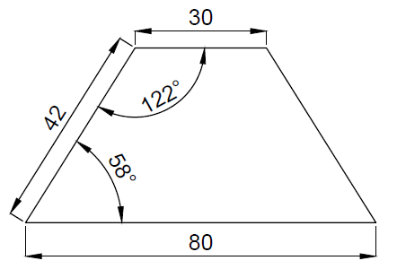
We will use the image below, and try learning all things we need to learn to be able to create something similar using AutoCAD.
We’ve learned a little how to use the coordinate system to create lines in AutoCAD. In this Session, we will forget a little about the Cartesian coordinate system.
It is true that using the Cartesian coordinate system we could draw lines with specified dimension, but this method is more convenient and is the one you will be making use of in the future.
Read more about how you can create lines and play with their angle
EXECUTION
To create the image above
STEP 1
Draw the line of 80 units
Click on LINE
Specify the first point
Make sure the ORTHO mode is ON, Move your mouse rightward, type 80 and Press Enter
Press Esc
STEP 2
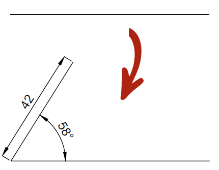
Start the second line from the first point of the 80 units line, and draw the second line with an inclination angle of 58 degrees.
STEP 3
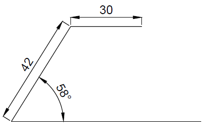
Draw the third line. It is a straight horizontal line.
STEP 4
All you have to do now is to create a line from the 2 open points shown on the figure in step 3.
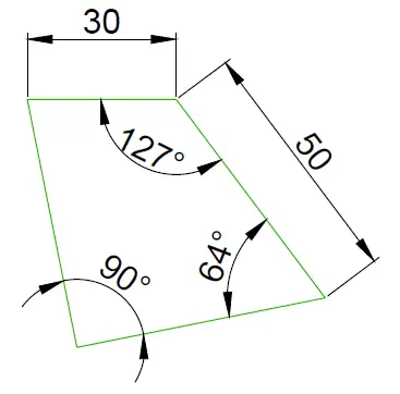
EXERCISE
Here is a good exercise that will help you practice what we have just learned. I will suggest youlearn how to use the ROTATE command in AutoCAD before trying to do the following exercise.
In case of difficulties, I would like you to know that I solved this step by step few days earlier.
Here is the first DAY. We will on this journey make use of all basic commands in AutoCAD.
The Attempt: Handing you enough skills that you give you confidence to continue learning auto-didactically.
LEARNING AUTOCAD BASICS
Today we will start from what you need to know on Day 1. You need to have visited theseAutoCAD tutorial before diving into the following. (Jump this step and read further down, if you feel that you can handle the rest of the content without needing anything else, feel free to do so).
COORDINATE SYSTEM
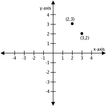
In AutoCAD, the Drawing Area is composed by a sheet in which every location has the particularity of having its own coordinate represented by x, y and z.
Since we are going to be solely working in 2D in this series, we can forget about the z component of the coordinate system.
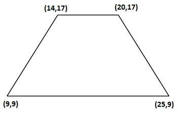
Looking at the following image, you will notice that each corner of the figure has a coordinates.
Though it is true you wont be using this a lot while drawing in AutoCAD, we will spend a minute talking about it. At this point, I will suggest you disable the Dynamic input before trying the following.
We will try creating the previous image using the coordinate system and the command window. It is simple, the concept will be to use the four points to draw the quadrilateral.
To do that using autoCAD:
1. Type LINE and Press Enter
2. Type 9,9 and Press Enter
3. Type 25,9 and Press Enter
4. Type 20,17 Press Enter
5. Type 14,17 Press Enter
6. Type 9,9 And Press Enter
7. Press Esc
The first step allows to activate the LINE command. (Learn more about the LINE command)
The second step allows to specify the starting point of the line and the same goes for next steps.
The last Step allows to Cancel the LINE command.
In AutoCAD stroking Esc (ESCAPE) allows to exit a command.
At this stage, you are not using the computer mouse, and you are require to pay close attention to the command windows while drawing. As we go, we will learn more about the command windows and how to use your mouse in AutoCAD.
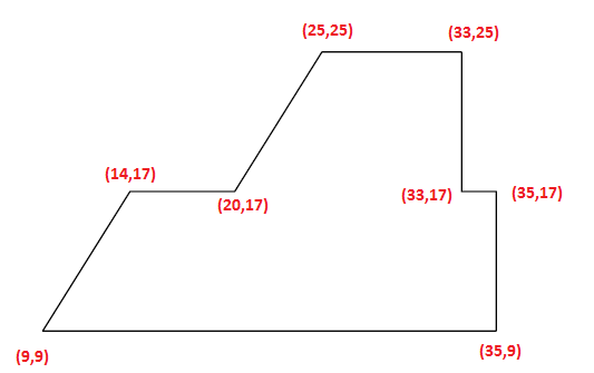
EXERCISE
Use the technique we have just learned to create the following.





 Royal Caribbean
 Royal Caribbean
 Royal Caribbean
 Royal Caribbean
 Royal Caribbean
 Royal Caribbean
 Royal Caribbean
 Royal Caribbean
 Royal Caribbean
 Royal Caribbean
 Royal Caribbean
 Royal Caribbean
 Royal Caribbean
 Royal Caribbean
 Royal Caribbean
 Royal Caribbean
 Royal Caribbean
 Royal Caribbean
 Royal Caribbean
 Royal Caribbean
 Royal Caribbean