Graphic World

Categories
Articles Learning

Introduction To Auto desk AutoCAD | DAY 12

Learn AutoCAD basics: DAY 12

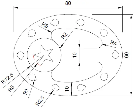
All here is a déjà-vu. Last session, we’ve learned how to use the ELLIPSE command in AutoCAD, in this session we are coming back with an even easier ellipse.

BUT, but now, the focus will be made on something totally different.

in Learn-AutoCAD-DAY-6, we have worked with the ARRAY command for the first time. Today you will need that command line more than EVER. And it is compulsory to have mastered it before trying the coming exercise.


LEARNING AUTOCAD BASICS

NOTE: Element in the array are equally spaced around the ellipse.

hey! If you have any confusion about this, Just leave a comment below. Let me know what is confusing about this, I will make it clear for you

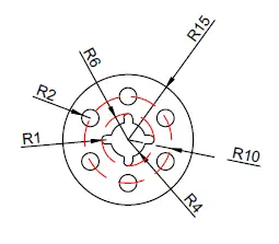
FIGURE 1

learn-AutoCAD

FIGURE 2

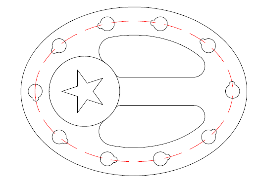
On the following image, the red line represent the PATH of the array. It resulted of an OFFSET of 5 units from the outer ellipse.
learn-AutoCAD

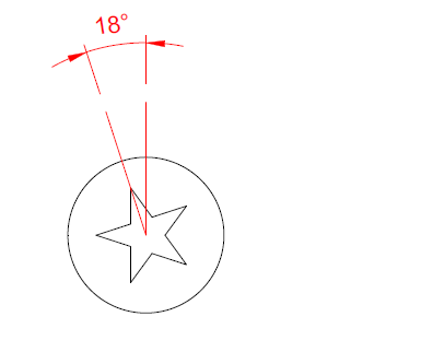
MORE DETAILS ABOUT THE STAR

learn-AutoCAD

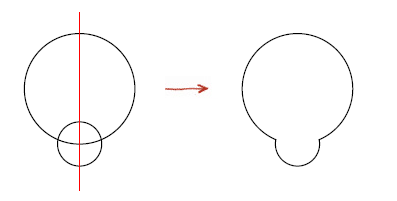
OBJECTS IN THE ARRAY

The object in the array is nothing but the following
learn-AutoCAD

You can find dimension of the circles on the first image above.

EXECUTION

The only thing that might be hard to accomplish here is the array. There is nothing like ARRAYELLIPSE in AutoCAD, what you need to do to create this array is using the ARRAYPATH.

To use the ARRAYPATH command using an ELLIPSE, you need to cut the ellipse into two, and use the ARRAYPATH on each of the side, that is it.

We would like to let you fight with it and figure it out yourself, using information we provided above.

Feel free to drop your opinion and concern in the comment section below.

Categories
Articles Learning

Introduction To Auto desk AutoCAD | DAY 6

Learn AutoCAD basics: DAY 6

In this session we will be challenging ourselves to learn how to play with the ARRAY command in AutoCAD.

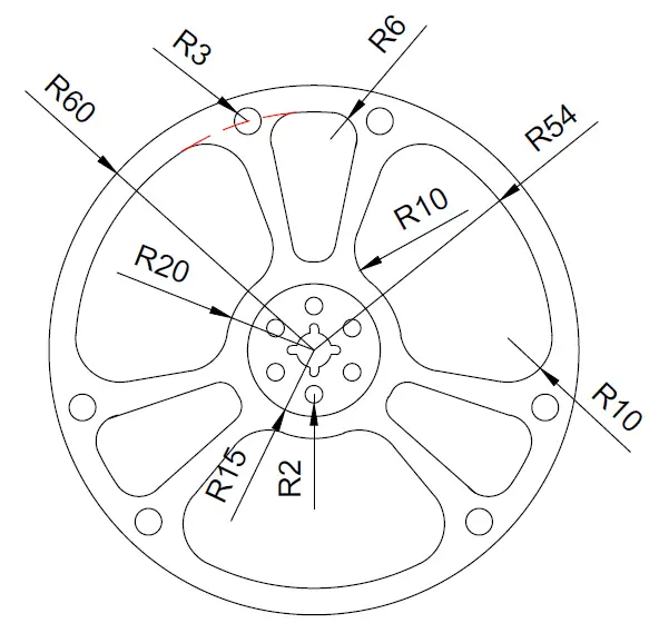
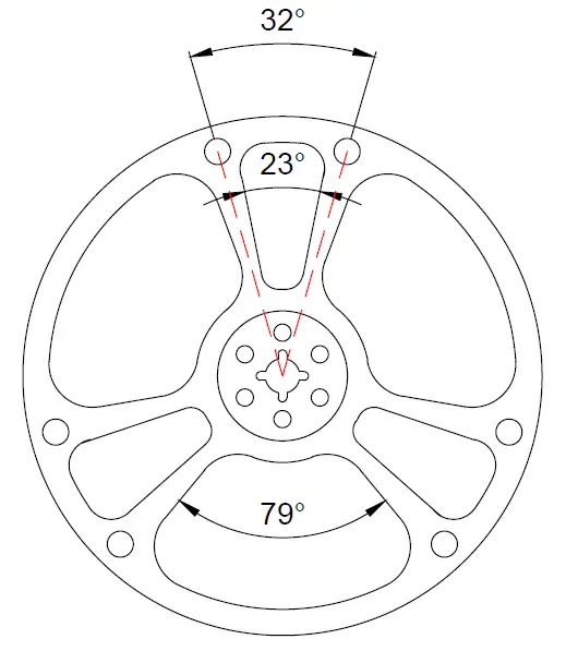
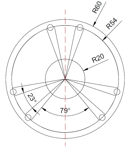
The image below is one of those that may best serve this purpose. It is to be noted that all slots are equally spaced around the circles.

Feel free to visit the post where we practiced and talked about the use of the ARRAY command in AutoCAD.

LEARNING AUTOCAD BASICS

There is not much to be done in this one but the proper use of the ARRAY command. All you will need is to have mastered the TRIM command, the LINE command, the FILLET command and theCIRCLE command.

Below we have split annotations in different figures to avoid having a bushy image. Combine all information available on the figures if you want to accurately replicate today’s exercise.

FIGURE 1

learn-AutoCAD

FIGURE 2

learn-AutoCAD

FIGURE 3

Piece in the center of the exercise.

learn-AutoCAD

EXECUTION

The following image might be helpful to you to have a good start

learn-AutoCAD

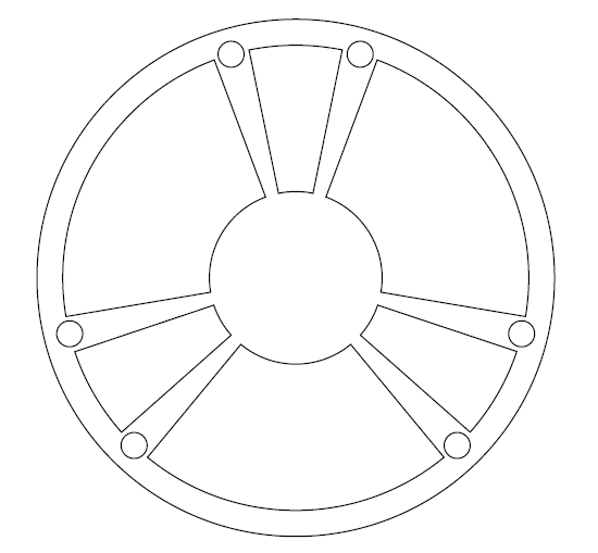
After proper TRIMMING, you will be left with the following

learn-AutoCAD

Now all you need to do is to use the FILLET command to round edges and create objects that are in the center of the figure.

Categories
Articles Learning

Introduction To Auto desk AutoCAD | DAY 1

Learn AutoCAD basics: DAY 1

Welcome to Learn AutoCAD 2D basics in 21 DAYS!

Here is the first DAY. We will on this journey make use of all basic commands in AutoCAD.

The  Attempt: Handing you enough skills that you give you confidence to continue learning auto-didactically.


LEARNING AUTOCAD BASICS

Today we will start from what you need to know on Day 1. You need to have visited theseAutoCAD tutorial before diving into the following. (Jump this step and read further down, if you feel that you can handle the rest of the content without needing anything else, feel free to do so).

COORDINATE SYSTEM

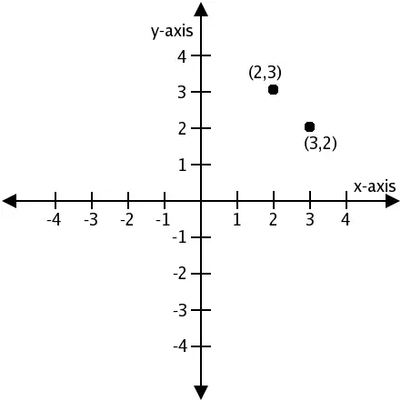
In AutoCAD, the Drawing Area is composed by a sheet in which every location has the particularity of having its own coordinate represented by x, y and z.

Learn-AutoCAD

Since we are going to be solely working in 2D in this series, we can forget about the z component of the coordinate system.

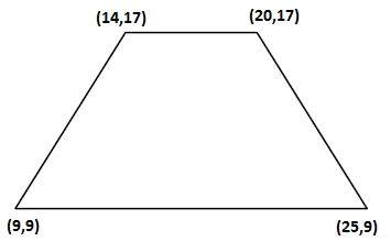
Looking at the following image, you will notice that each corner of the figure has a coordinates.

Learn-AutoCAD

Though it is true you wont be using this a lot while drawing in AutoCAD, we will spend a minute talking about it. At this point, I will suggest you disable the Dynamic input before trying the following.

We will try creating the previous image using the coordinate system and the command window. It is simple, the concept will be to use the four points to draw the quadrilateral.

To do that using autoCAD:

1. Type LINE and Press Enter
2. Type 9,9 and Press Enter
3. Type 25,9 and Press Enter
4. Type 20,17 Press Enter
5. Type 14,17 Press Enter
6. Type 9,9 And Press Enter
7. Press Esc

The first step allows to activate the LINE command. (Learn more about the LINE command)

The second step allows to specify the starting point of the line and the same goes for next steps.

The last Step allows to Cancel the LINE command.

In AutoCAD stroking Esc (ESCAPE) allows to exit a command.

At this stage, you are not using the computer mouse, and you are require to pay close attention to the command windows while drawing. As we go, we will learn more about the command windows and how to use your mouse in AutoCAD.

EXERCISE

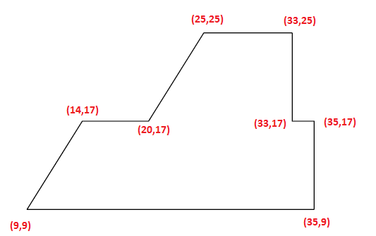
Use the technique we have just learned to create the following.

learn-AutoCAD

Note you can start from any point.