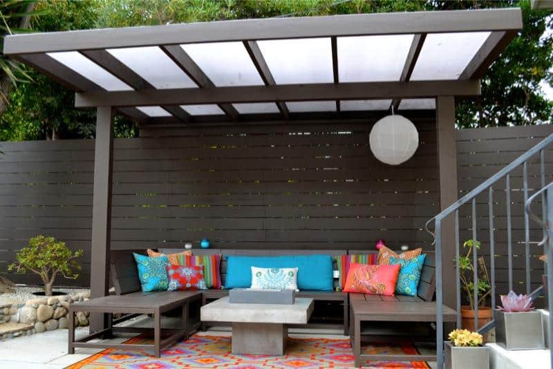
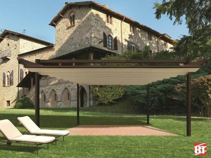
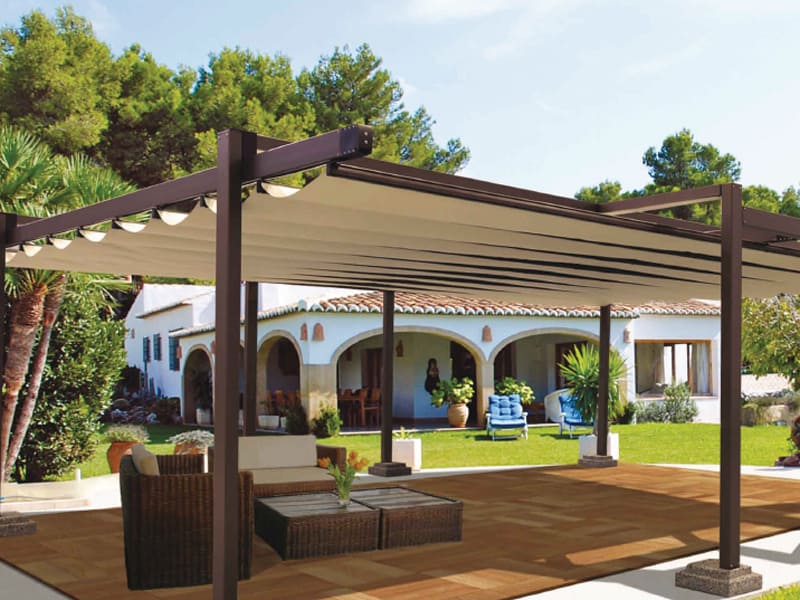
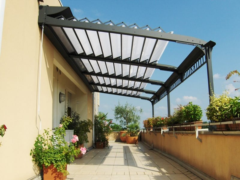
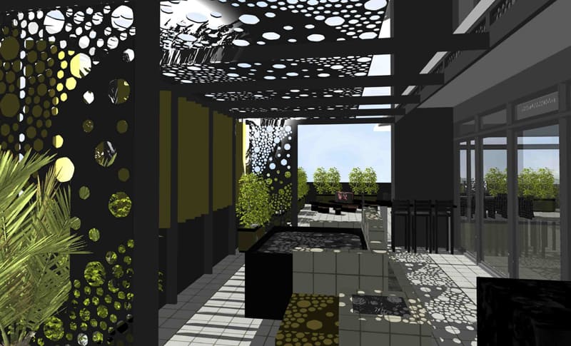
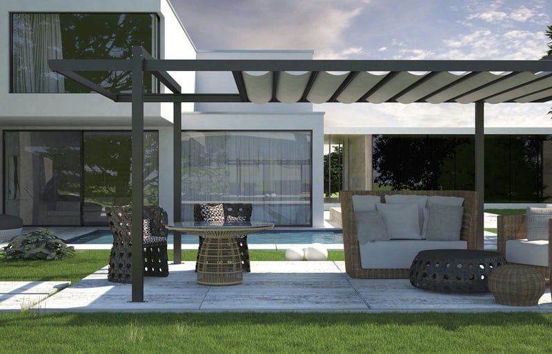
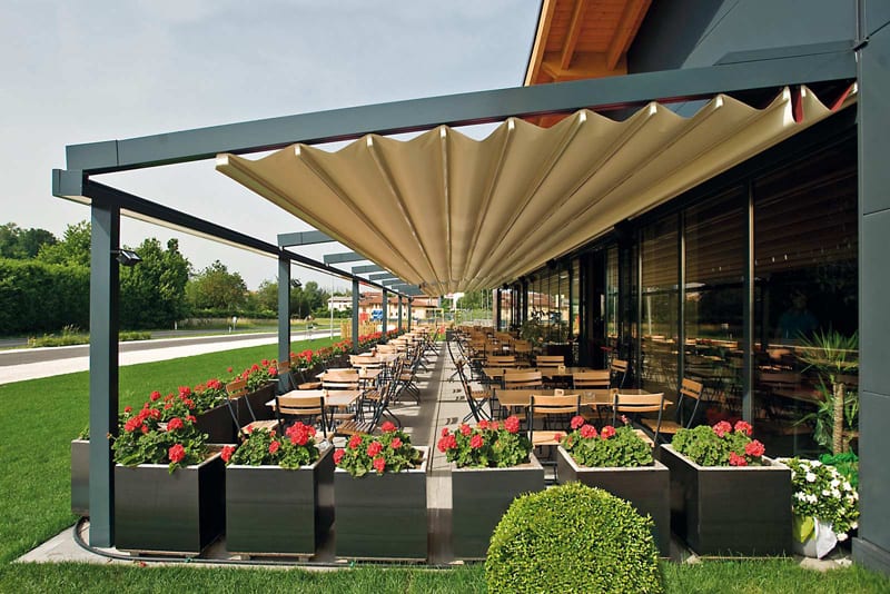
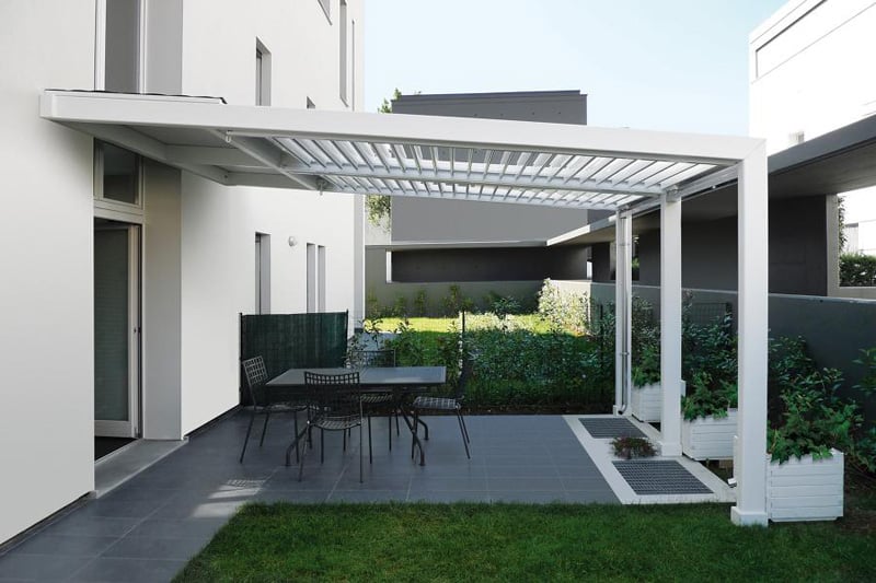
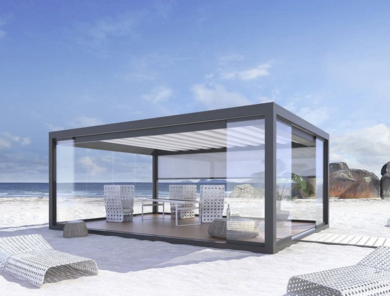
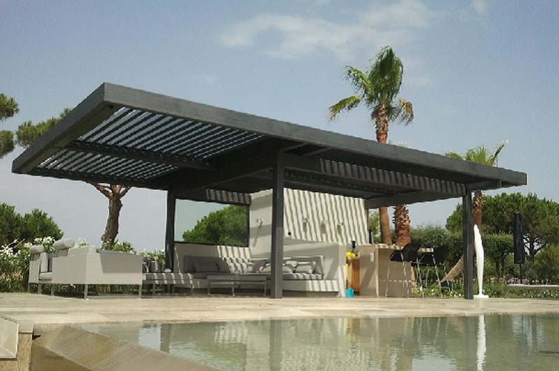
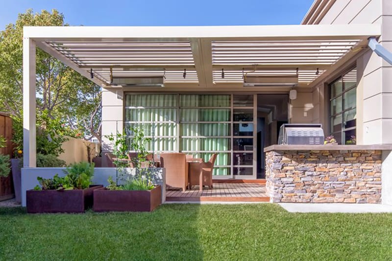
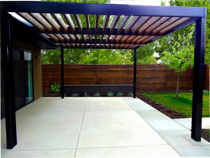
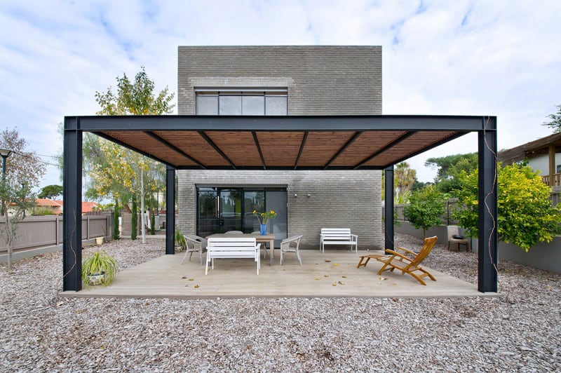
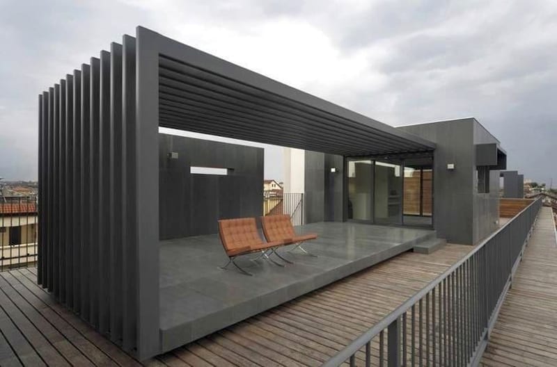
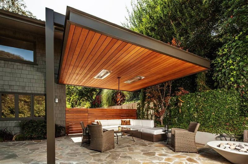
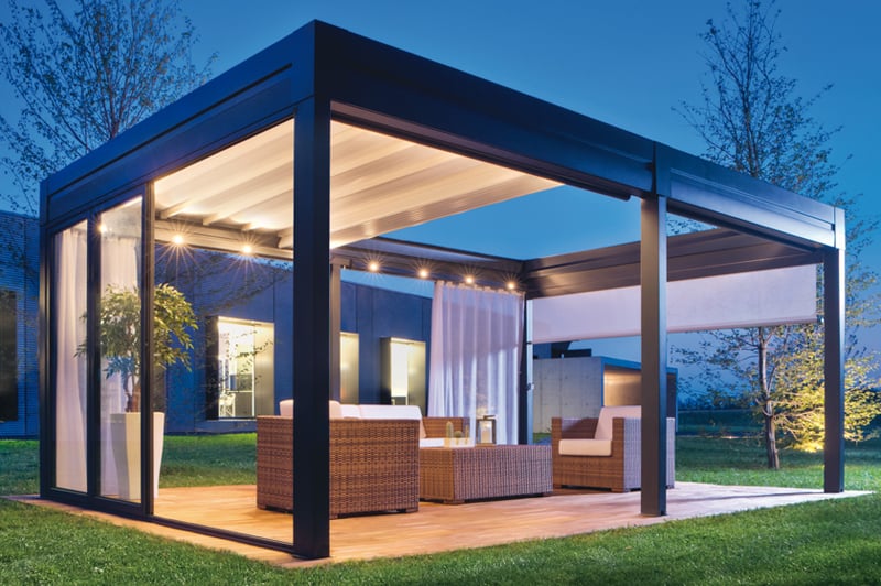
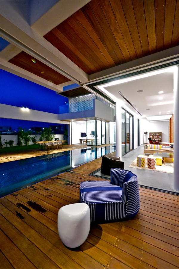
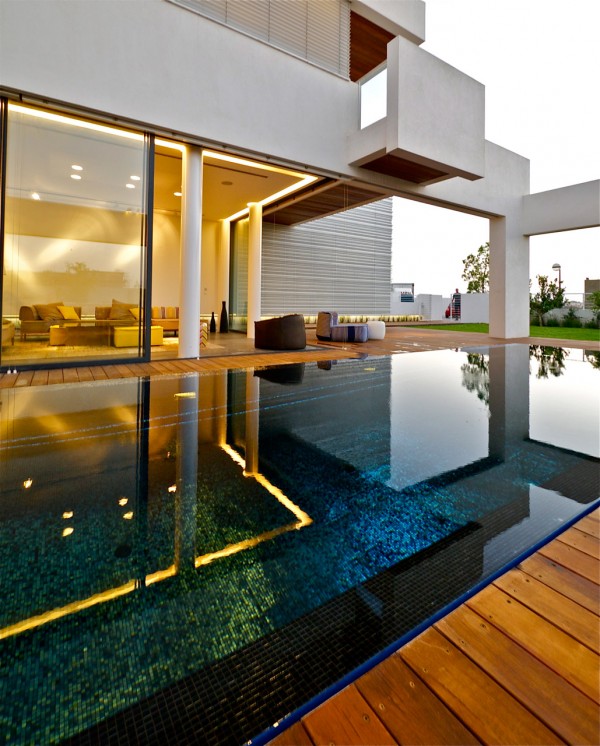
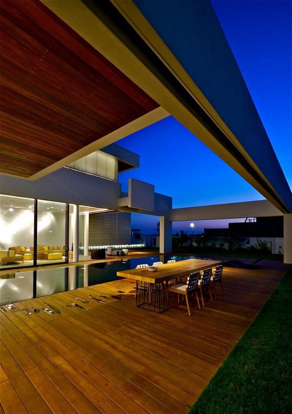
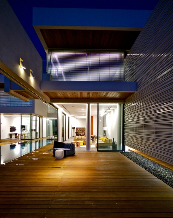
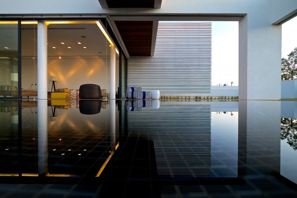
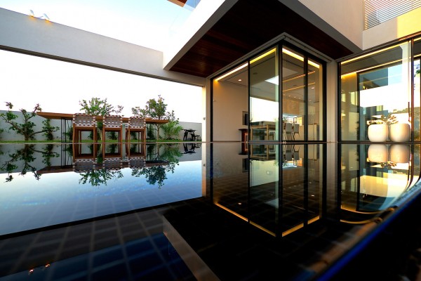
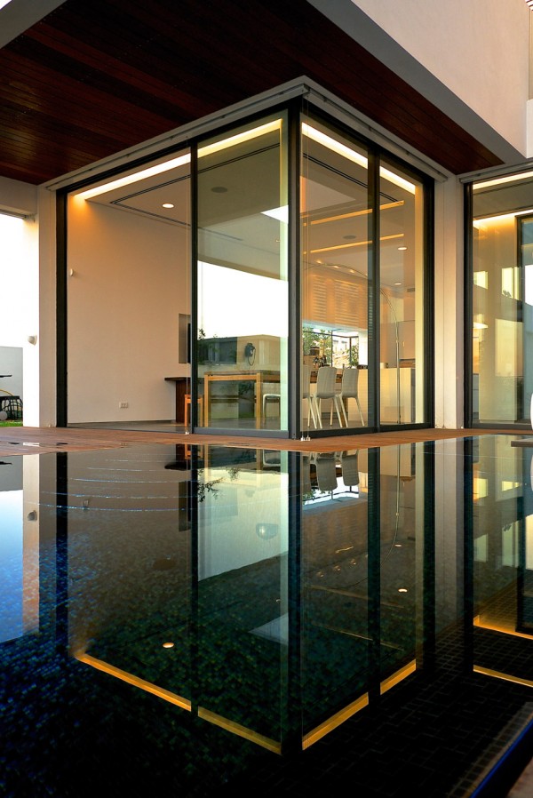
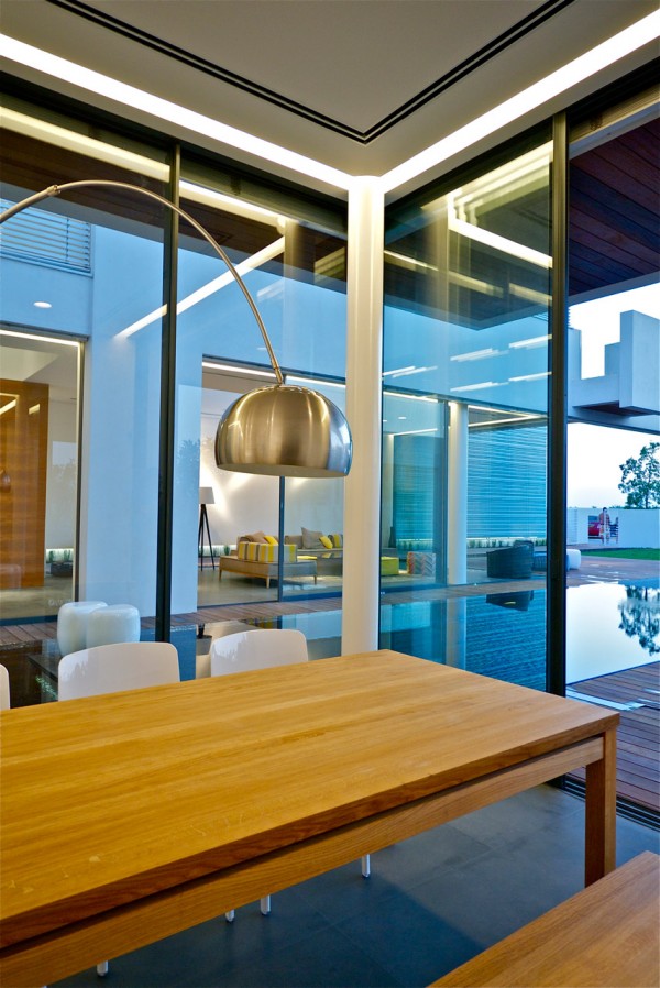
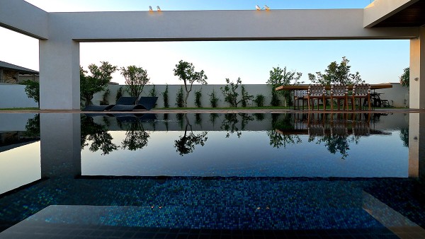
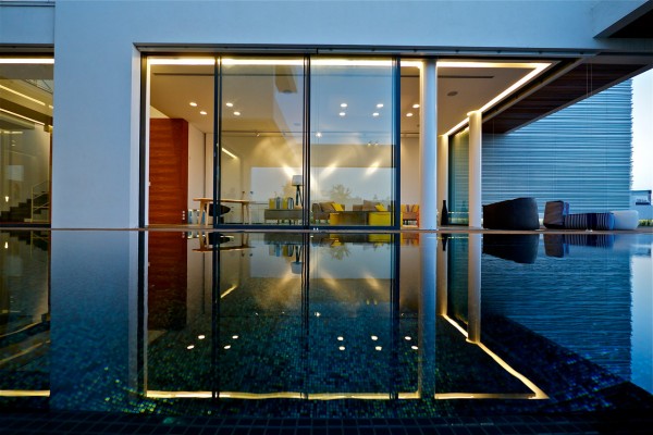
A pergola is an ideal for creating beautiful environments in your garden and terrace. Pergolas are usually custom-built and made of wood, but aluminum and vinyl pergolas are growing in popularity because they last a long time and need almost no maintenance to continue looking good. Since aluminum and vinyl require special tools and techniques to work with, these materials are most commonly available as pre-manufactured kits. Add beauty and shade without the maintenance of wood with an Aluminum Pergola. Aluminum pergola is the right choice to be applied in a place that experiences the changing climates very often. Aluminum is a lightweight material and arguably cheap. Besides, this is also stainless. This material is suitable to be applied at home with a variety of themes even if you apply a modern theme in your home. Basically, garden will always fit combined with any theme. This also applies for the pergola. Therefore in this article we will show some examples of pergola that use aluminum as the primary material. Enjoy our beautiful collection of 20 Aluminum Pergola Design Ideas. Check this out.
We previously visited three spectacular Thai villas at the amazing luxury getaway on the island of Koh Samui, and we just can’t help going back for more. So, come with us once again to Thailand’s second-largest island after Phuket, as we visit yet another villa at Samujana.
1 |
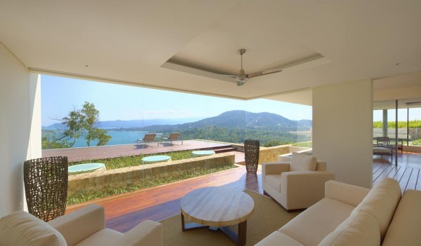
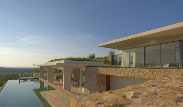
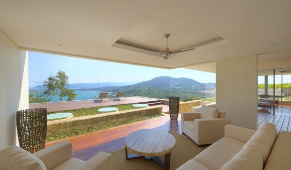
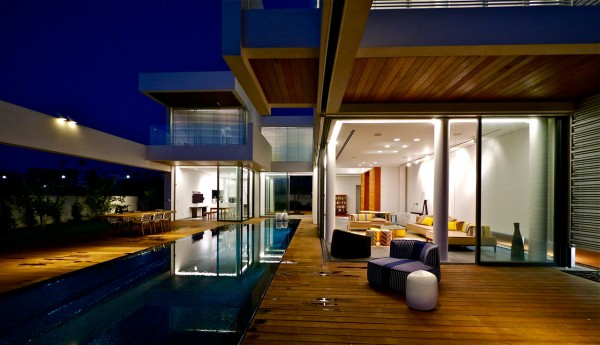
Situated on a serene corner plot of the luxury villa resort, the five bedroom, five bathroom holiday home is flooded with fresh contemporary luxury. An airy open plan living area spills out onto a generous sun deck where the views of natural beauty can soothe the soul. An outdoor lounge setup brings further opportunity for relaxing or entertaining in the fresh air, and a private saltwater infinity pool provides the perfect place to cool off or clock up a few laps as part of your exercise regime.
3 |
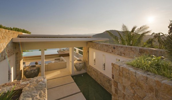
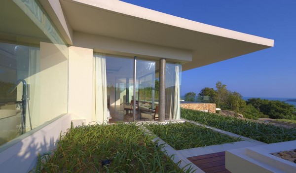
Stony walls soften the look of the contemporary architecture, and make the building appear more at one with the surrounding beaches and natural beauty.
4 |
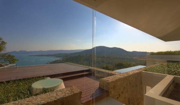
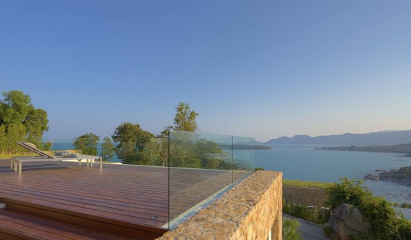
The massive sun deck basks in the view of a glorious panorama.
5 |
6 |
7 |
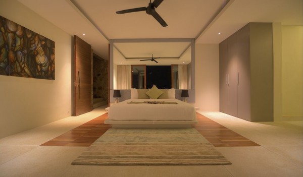
The furniture and décor has been kept white, bright and simple throughout the vacation villa, giving the place a clean and uncomplicated look.
8 |
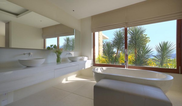
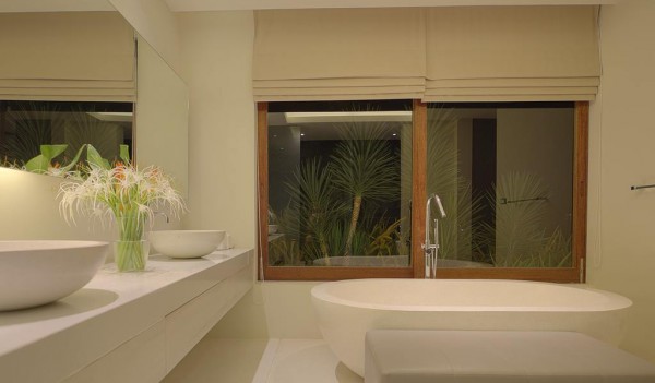
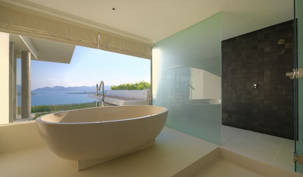
Each of the five huge en-suite bathrooms offer rainfall showers and modern freestanding bathtubs, along with exquisite finishes and tropical landscapedgarden views.
9 |
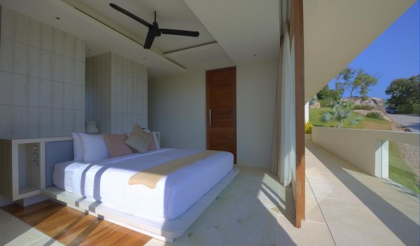
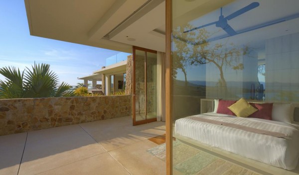
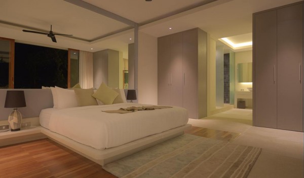
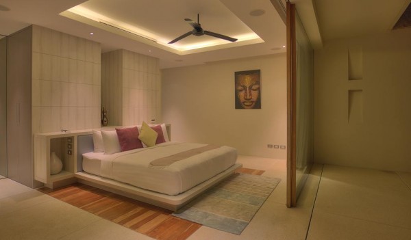
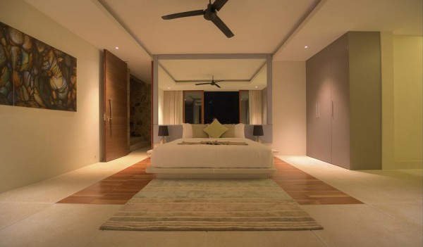
King sized contemporary platform beds fill the bedrooms, providing plenty of sleep space to stretch out in. Retractable glass doors open up the slumber zones to the great outdoors and private terraces.
10 |
11 |
This double vanity unit holds twin sinks for tandem washing and preening.
12 |
13 |
14 |
15 |
16 |
17 |
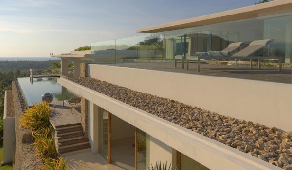
Glass balustrades have been installed around the sprawling sun deck to ensure that absolutely not one bit of the splendid view is obscured from the daily sun worshippers.
18 |
19 |
20 |
21 |
22 |
23 |
24 |
25 |
26 |
27 |
28 |
29 |
30 |
31 |
Live-in staff at the villa make sure that the lucky guests have everything they need in the holiday hideaway.
32 |
33 |
34 |
35 |
36 |
37 |
38 |
Did you like this article?
Share it on any of the social media channels below to give us your vote.
Clean modern lines, floor to ceiling glass windows, plenty of ventilation, expansive pools, and beautiful landscape seem to be the characteristics common to most of their designs.
This 600 square meter beauty was completed by the firm in 2012.
13 |
This is another villa designed by them which is about 510 square meter in size.
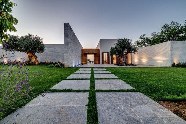
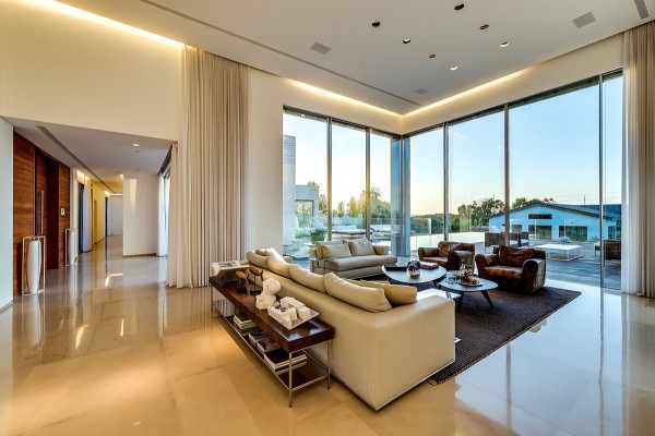
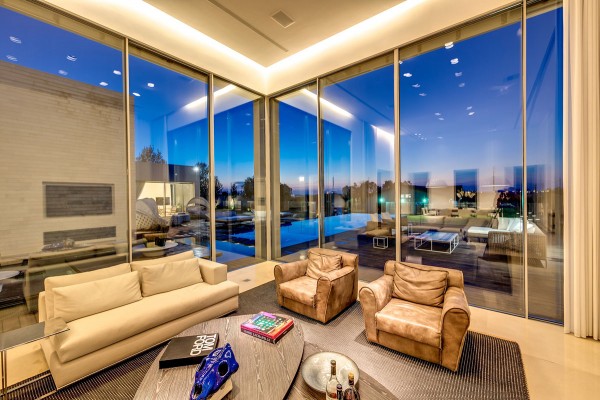
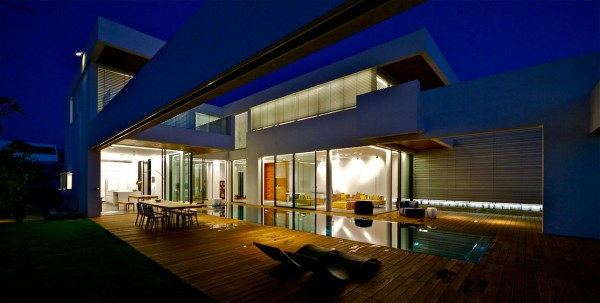
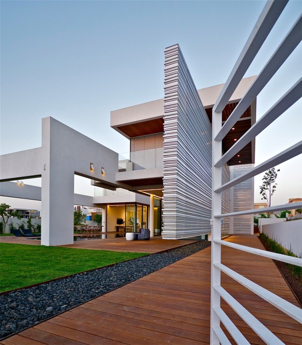
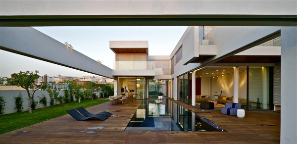
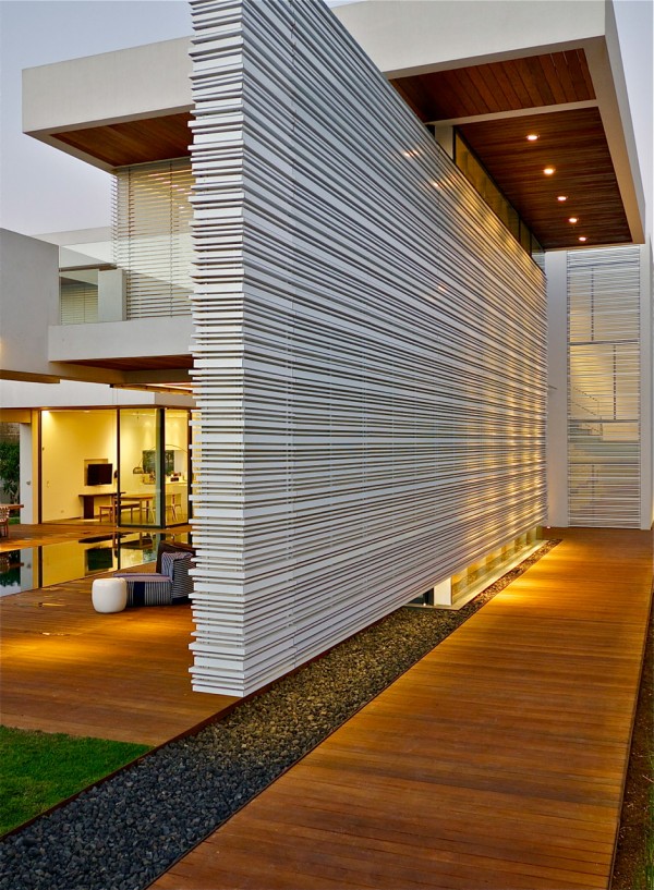
…design took into consideration the impact of the natural factors on the edifice, including wind directions, sun and natural light allowing the users to enjoy the sea breeze and natural ventilation. The interior and exterior spaces were designed as “a whole”. Minimal structure, transparent walls and long vistas to the yard and pool helped blur the borders between the inside and the outside. A multi-functional wall stretching from one side of the house to the other is seen as though it is floating. The wall is covered with aluminum profiles in various sections. These sections have an esthetic side creating breathtaking views as one is gazing to the entrance of the house. On top of that, the profiles are insulated and have a role in decreasing energy lost in the house. The materials used were basic and natural – teak wood, aluminum, glass and grey basalt floor finish.
20 |
21 |
22 |
23 |
24 |
25 |
26 |
27 |
28 |
29 |
This is yet another one at 600 square meter.
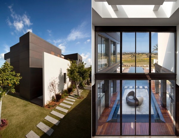
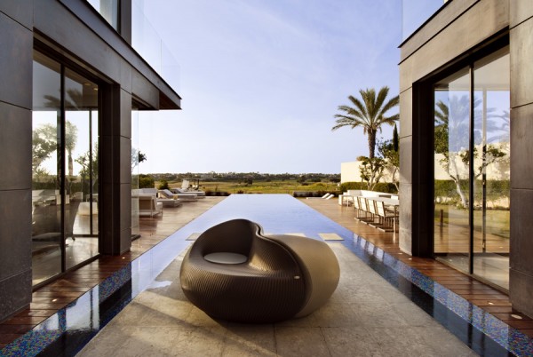
The villa is located in the new Golf quarter in Ceasaria, and the site’s back yard is facing the golf courts. It was designed as a sealed sculptural mass towards the street covered in a bronze plate. The gates leads to an enclosed patio, enclosed with two 4m high bronzedoors. The patio creates a buffer zone between the house and the street. Once entering the house an uninterrupted vista of the infinity pool, the yard and the golf courts is exposed. Similar to the street face, the majority of the house is covered with bronze panels. Bronze was also used for the window frame to create a comprehensive look for the house. The interior design of the house is characterized in grey-white palette with different materials and textures.
Did you like this article?
Share it on any of the social media channels below to give us your vote.
Lance Evans takes you on a day-long crash course of this powerful open source 3D application.
Until the day when desktop holography becomes a reality, 3D will remain the wholly grail of the graphics world. But 3D can be a very technical craft. And each 3D program has its own idiosyncrasies, making it all a bit daunting.
I cut my 3D chops on many programs that are now long dead and forgotten. Blender is one program I’ve wanted to learn for many years. I’ve even downloaded and installed it a few times, but fell short on the follow-through to learn it. Writing this article is my personal impetus to finally get to learning it. Perhaps it can be your impetus as well. Let’s see where we can take this in just 24 hours.
Why choose Blender?
Blender has many qualities that include years of steady development, a prized commodity in either commercial or open source projects. This has netted a broad range of capabilities, beyond even its full range of 3D modeling and animation tools.
For example, Blender has video editing, camera tracking, compositing, and even game creation tools all built right in. The fact that it’s open source and completely free is also an unbeatable perk! (Though donations to the Blender Foundation are a good idea.) With all this power, Blender’s toolset is often directly compared to top programs in the 3D field costing thousands, like Mayaor 3ds Max.
Naysayers may complain it lacks centralized support, since there is no commercial publisher with a help staff. However there is ample support onlineon many sites, and even a real time IRC chat option. This means nights and weekend support too! Plus, the Blender community can be uniquely generous with its help.
The other knock is Blender’s much smaller market share, which means there are perhaps fewer companies looking to hire Blender artists. Having said that, know that this is changing and there are sites like the Blender Network that specialize in matching Blender artists with employers. And even mainstream job sites are getting more Blender savvy every day.
None of this is even an issue if you run your own shop or are just doing your own thing. Then all that matters are the final renderings. And few clients know or care about all this techno-geek talk.
Blender’s own jobs website, and it’s gaining ground on other job boards as well
My first hour with Blender: installing and learning the interface
I went up to Blender’s website , clicked on the ‘Download’ link, and chose between the installers available for Mac, Windows, Linux and even FreeBSD. (And made a small donation while there!) Installation was almost crazy-easy, and fast. Which is common for most open source programs.
Blender splash page
Once installed, I booted it up like a kid on Christmas morning. The splash page had a number of links, including one to the official Blender manual online. The manual is an excellent resource, but perhaps a bit better suited to those that already have an introduction to both 3D and Blender.
Blender’s official online manual
Upon first viewing, Blender’s interface can be overwhelming. But it isn’t as complicated as it first looks. Once you understand the logical thought process it becomes much less daunting. Logic-wise it’s rather similar to Adobe programs like Photoshop or InDesign.
Blender’s default user interface. See the text for a quick explanation of its UI
The default Blender interface is made up of four areas. (A) in the image above is called the Toolbar, a collection of the most commonly used tools. (B) is the 3D Viewport, or work window. (C) is a vertical stacking of many control/preference/properties interfaces, which again, is just like Adobe products you know. (D) is the timeline, for animation work. You might be familiar with this from programs like After Effects.
Understanding these basics makes Blender all the more approachable. Although not necessarily more useable. Before looking at any instructions, I felt compelled to muck about with the buttons, doodads and doohickeys, and hoped to find my way around. But I’ll admit that I wasn’t too successful. I began to realize that Blender wasn’t quite as intuitive – at least for me – as I had hoped.
So I started to explore what alternative ways I could go about learning it, beyond the button-poking. I quickly found out there are quite a few learning options out there.
An extreme example of multi-monitor support
Hours two-four: organizing my education
Starting my second hour with Blender, I began hunting for ways to learn it. I started out the way many of you would, by looking online for books. A quick search turned up dozens of books which included titles such as ‘Blender 3D Cookbook’ and ‘Blender Basics’ (both from PACKT Publishing), and ‘Blender for Dummies’ (John Wiley & Sons), all recently published as print and Kindle editions.
I ordered a few of these books for download. Which books best fit your learning style is up to you. As might be expected by the title, the ‘Dummies’ books take extra pains to make easing into a new subject as painless as possible, so are a good place to start. But they also tend to not go as deep as other offerings. All the books were well written and took me step by step.
And while I began learning from these books, I had to acknowledge that whether it’s our cultural evolution, or just me getting older, I found it harder to read this tech material than I used to. So I began looking for other ways to learn.
Hours four-10: video education, part one
Again, I didn’t do anything different here than most of you, I went trolling around YouTube with search phrases like ‘learn blender’, which gave a return of 157,000 videos. I’m sure most had more to do with making a good smoothie, but still, there were hundreds on Blender 3D.
An advanced subject: creating a city in Blender
Some of the most popular Blender tutorial channels included Blender for Noobswith over 27k subscribers, Blender Guru with over 153k subscribers (see the amazing architecture video!), and tutor4u with over 172k subscribers.
Pure fun: Minions in Blender!
Jacob Lewis offers a 2014 updated 10-part video series called ‘Blender Absolute Beginner Tutorial’ with about 380k subscribers. One video that is seriously worth a look is Max Coulfield’s great Blender sculpture timelapse.
‘Sculpting’ a young female head and shoulders
I spent time finding and then watching many videos, and at this point I had clocked in roughly 10 hours of working on the Blender project, across two or three days. Trying to do it all in one day would surely have exploded my tiny head.
Hours 10-15: video education, part two
After viewing YouTube tutorials for a bit, I will admit to a bias against any that begin with “Yo-yo fellas… wassup?” An experience that can leave you wanting more formally prepared material.
So I finally did something that many of you might not actually do. I contacted Ton Roosendaal, the original creator of Blender, and now the Chairman of the Blender Foundation. He was gracious and we exchanged a number of emails. At his suggestion, I got in touch with Jonathan Williamson, a co-founder and instructor at CG Cookie, an online computer graphics video education resource. CG Cookie has courseware for Blender, as well as other subjects like creative concepting and Unity game development.
CG Cookie offers online video courseware on Blender
CG Cookie offers what they call ‘Learning Flows’ for Blender, which contains 141 separate video installments. These are broken down into 9 sections, with topics like modeling, lighting, etc. The first module in the series is ‘Blender Basics’, which they make available at no cost. It contains six videos that run about a half hour total. Over the next few days I watched the intro videos, and as many of the follow-up sections as I could. All the while popping back to Blender to try things out.
Hour 15 and beyond…
I also touched base with Anja, who runs the Blender Shop on blender.org. She provided a long list of Blender learning resources, which we have reprinted at the end of the article.
So by the time I was nearing my 18th hour with all of this, I was feeling like I was in a fairly good place. By that I mean I could navigate around the interface with aplomb, I could create, modify, and texture map models (with limits on complexity), light them, and render out basic animations. In other words, I could knock out basic day-to-day 3D work. No character modeling, video editing or compositing, I’ll leave that for another day.
If this was for myself instead of an article it would have gone faster. One book and one video series would have been fine. I’m sure you’ll keep things simpler.
So what are you waiting for? Download it now, and let us know how your learning curve goes!
Resources (from Anja at Blender Shop)
A good way to learn Blender if you don’t have experience with 3D
programs is to start with Blender’s own tutorials and manual.
You can find lots of free tutorials on the internet about learning Blender.
Here are some links with lots of information:
http://wiki.blender.org/index.php/Doc:2.6/Tutorials
We have hit the last DAY of the series, and we hope we have provided you with some insight and that those will help you and give you more confidence to walk further toward your being a Pro AutoCAD user.
In this session we will rush a little bit, and learn few things you need to learn before closing.
Things we are going to be pushing forward in the following lines, are
How to you write a text in AutoCAD
Working with Layers in AutoCAD
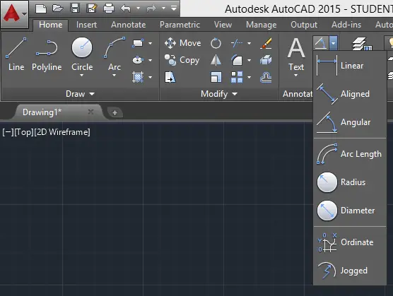
How to annotate in AutoCAD
All will be covered just from the basics point of view, but the most important will be covered.
LEARNING AUTOCAD BASICS
ANNOTATION IN AUTOCAD
Learn more about Annotation in AutoCAD
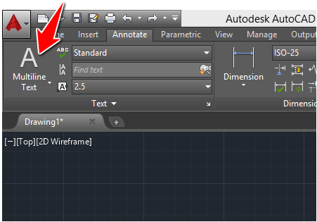
TEXT IN AUTOCAD
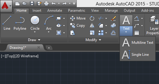
This can also be reached from the HOME tab
annotation
WORKING WITH LAYERS IN AUTOCAD
hey! If you have any confusion about this, Just leave a comment below. Let me know what is confusing about this, I will make it clear for you
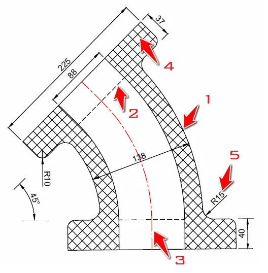
The following image will serve as an exercise.
This is nothing but the image we worked on DAY 19, Now the task will be to create 5 Layers, and place each of the part of this project in its appropriate layer.
Layer 1: the Object itself
Layer 2: The Dashed lines
Layer 3: The center line
Layer 4: HATCH pattern
Layer 5: Annotations
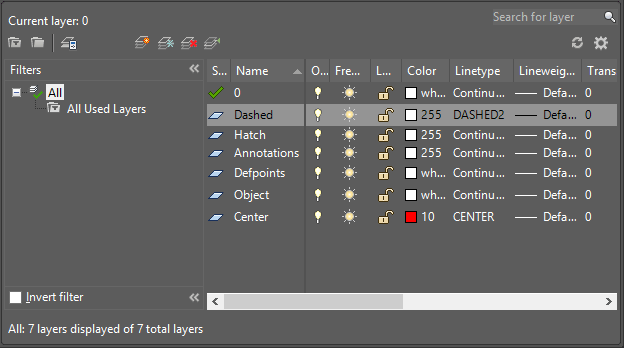
Your layer properties manager window should look like the following.
Nothing new under the sun. Here we come again with a bushy one.
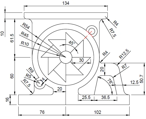
Today, you will need the ARRAY command, the FILLET command and the OFFSET command (we made an extensive use of the OFFSET command in DAY 7). There is no need to mention that you will need the LINE command, the CIRCLE command, may be the ROTATE command too.
LEARN AUTOCAD BASICS
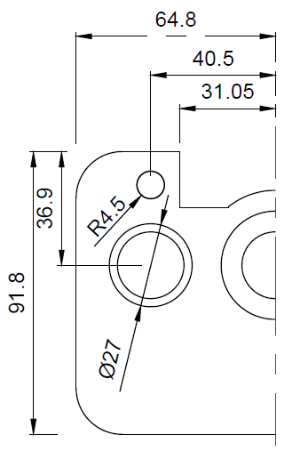
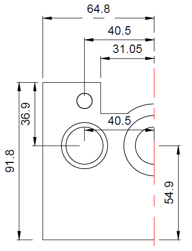
FIGURE 1
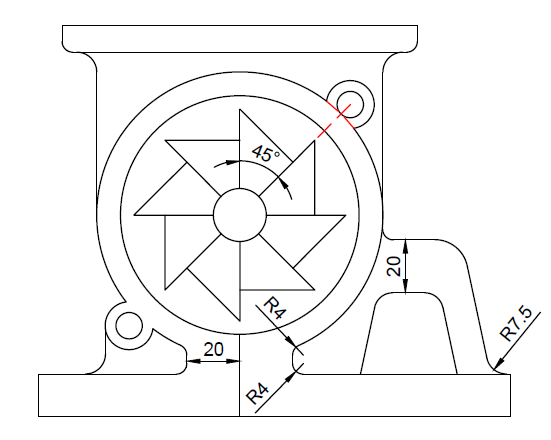
FIGURE 2
The following image provides some additional information needed to perform the exercise with success.
For the sake of exercising with the HATCH command, you can HATCH the above project at the end if you wish.
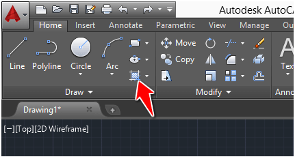
Today, we have a pretty straightforward image to replicate, and part of the task here is to use the HATCH command once the image is created.
The image below can help you locate the HATCH command.
To sum it up, they wont be lots of difficulties in this one. You need to be able to place objects however it is required in a 2D space. We tend to the end of this series, and one thing that you need to learn with these is to master the 2D space in AutoCAD. If you wish to jump into the 3D world later on, it is necessary you master how to move element in a 2D space.
DAY 18, a lot must have happened by now. We wish you have been learning something valuable since the beginning of the series.
Here comes one of the easiest one of the series. You will agree with us that if this exercise appeared earlier that would look more difficult than it looks at this point. With all you have accomplished so far, this should be a piece of cake, just helping you retrain some of the stuff you have been learning here with the Learn AutoCAD Basics in 21 Days series.
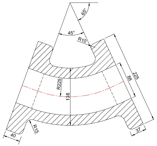
In this session, it will be required to use the ROTATE command and the OFFSET command a lot.
LEARN AUTOCAD BASICS
FIGURE 1
hey! If you have any confusion about this, Just leave a comment below. Let me know what is confusing about this, I will make it clear for you
FIGURE 2
The following figure is the exercise without annotation.
There is not much hardship in the session we are about to have. This should be a piece of cake if you have been following the series since DAY 1.
Just for the sake of knowing, here are couple of things you need to know before diving into today’s exercise:
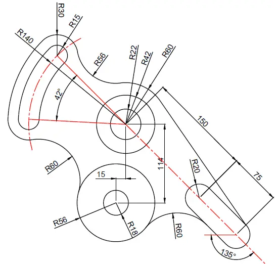
You need to have mastered the use of MIRROR command. You can avoid using it but using it the right way to go. After creating those arcs, Use the MIRROR command to create a mirrored copy on the other side. The red lines can serve as a line of symmetry.
To create the arcs, you need to use the feature Tan Tan Radius of the CIRCLE command. If this is the first time you hear about this, it is not late to go and check it out.
LEARN AUTOCAD BASICS
FIGURE 1
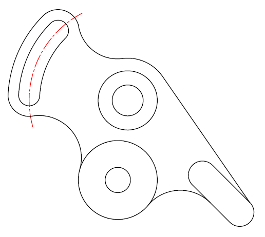
FIGURE 2
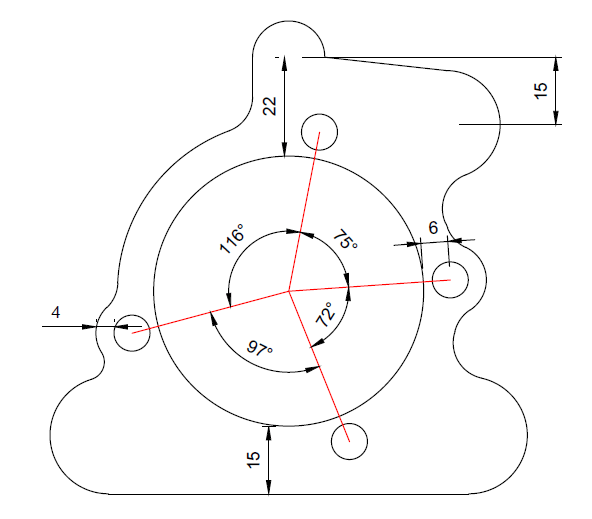
To avoid the preceding image to be too bushy, we’ve split information. You can find the remaining part of the information you need in the following picture.
In this Learn AutoCAD basics DAY, we have learned how to grow an array on an ellipse. Today we are going to combine that skill with others to complete today’s project.
That being said, we will suggest you to master the experiment we made on DAY 12 and the use of the ARRAY command in AutoCAD before trying this one out.
LEARNING AUTOCAD BASICS
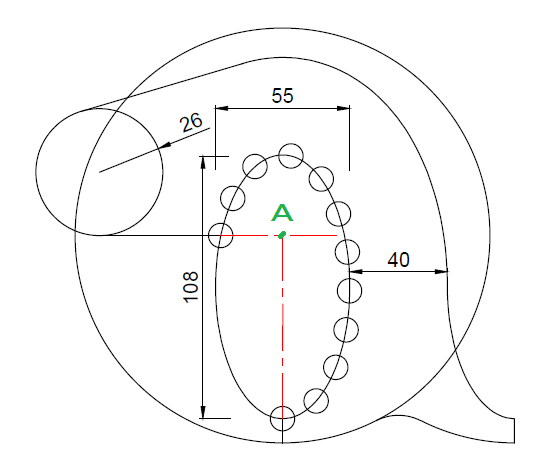
The following is the image of today’s experiment.
hey! If you have any confusion about this, Just leave a comment below. Let me know what is confusing about this, I will make it clear for you
EXECUTION
Now, we would love to provide the following images. Those will contribute to make you see clearly how you should proceed .
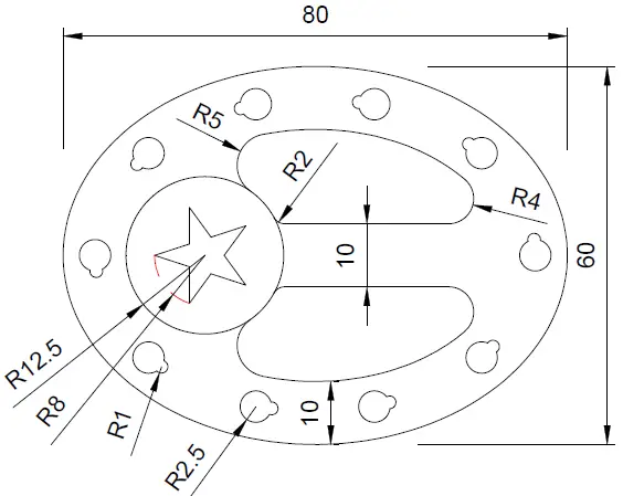
You can notice an ellipse of 55 x 108 on the figure below, it is what you have to use to create the array. Those small circles are equally spaced around the path of the array.
The center of the Big circle is shown on the image below and denoted by A.
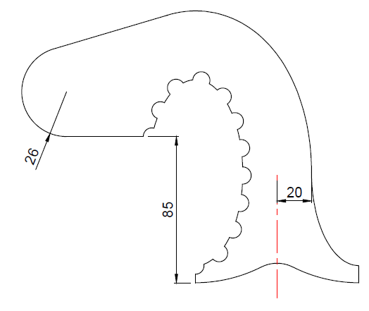
The following image gives a dimension that will be important while designing.
The red line on the last image shows a line of symmetry that will be used to get the down part of the object completed.
Note you will be required to use the OFFSET command in this exercise.
In this post, we are going to be perfecting how to handle positioning in AutoCAD.
The Object SNAP mode will be important for this session, The exercise itself is an easy one, but you need to be a bit cautious about where each of the object is placed in the project.
The use of the OFFSET command will be helpful and the ability to create a circle with the feature Tan, Tan, Radius.
LEARNING AUTOCAD BASICS
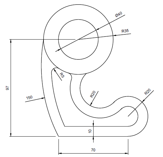
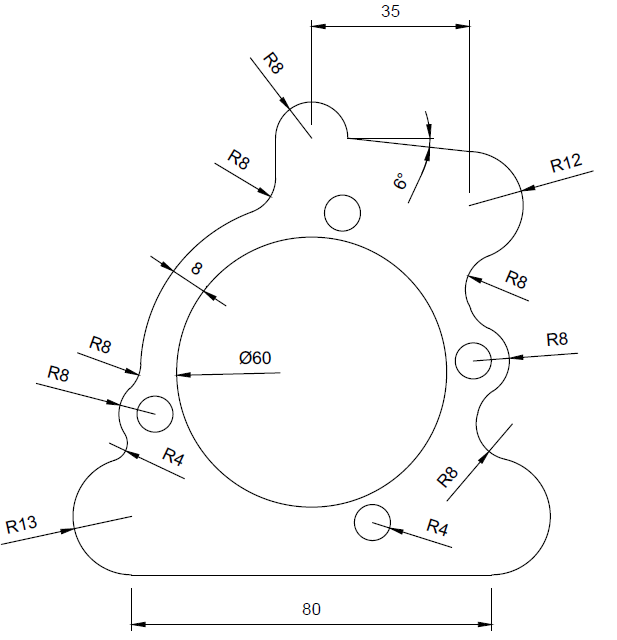
The following is the exercise we are going to be using in this session.
FIGURE 1
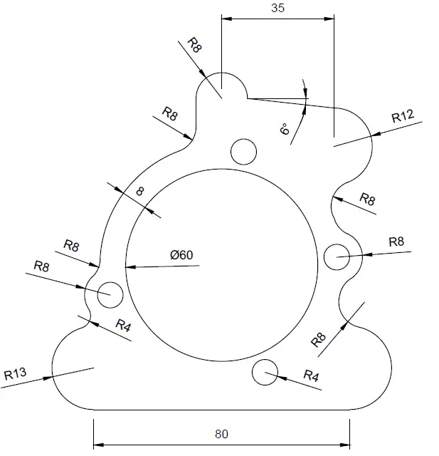
Additional important information are brought using the following image.
FIGURE 2
hey! If you have any confusion about this, Just leave a comment below. Let me know what is confusing about this, I will make it clear for you
EXECUTION
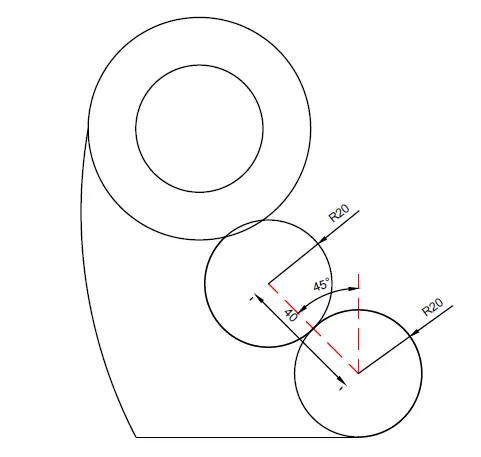
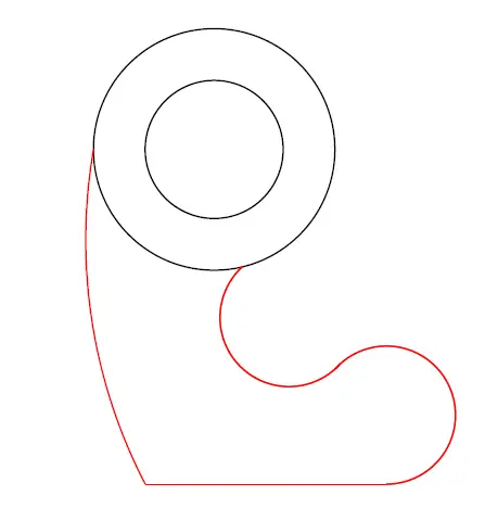
The following is the key image which will help complete this project.
You need to first get the above image then Trim it, and you should get the following.
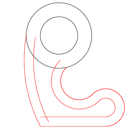
What you need to do now is: Give the red part an OFFSET of 10 units, and you will end up with the following.
It is all clear now, you surely know what to do next to complete today’s task. Do not forget the two FILLET of R5 we have just below the two circles.
In this session there will be nothing difficult, except the fact that it will help you develop yoursense of analysis while using AutoCAD.
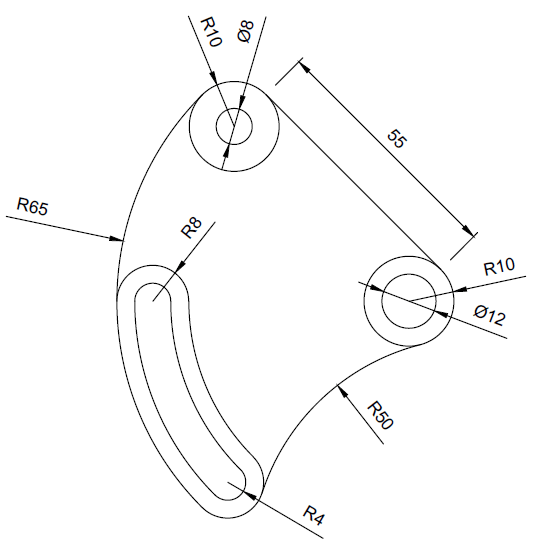
Looking at the exercise below, you should be able to, from a first look, determine all commands you need to be able to accurately replicate the object of today’s experiment.
You by now possess all you need to be able to complete the following without any problem
LEARNING AUTOCAD BASICS
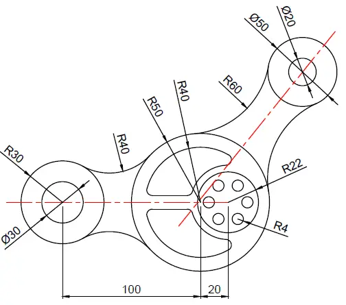
FIGURE 1
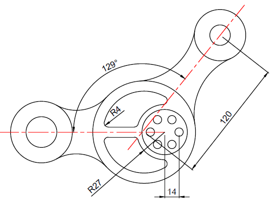
FIGURE 2
hey! If you have any confusion about this, Just leave a comment below. Let me know what is confusing about this, I will make it clear for you
EXECUTION
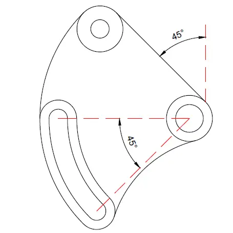
For some, figures above will not be self-explanatory enough, that is why we are bringing the following image. Pay attention to the skeleton-image used while creating the project, you will notice this is even easier that what it seemed at first.
Our suggestion will be to start from the base line (line of 80 units). All information are provided for this not to be a headache.
Feel free to drop a couple of words below in case of difficulties.
If you remember what we did in Learn AutoCAD DAY 7, you will notice that the following is quite similar to it. We had to learn how to use the OFFSET command and we have been using it throughout since sometime now. In this session, you have to use it as well.
LEARNING AUTOCAD BASICS
We have bent this to push you to use the ROTATE command. But it you have eyes to look at the image in a more engineering point of view, you will quickly notice that you can draw the object without inclination angle and bending it just at the end of the project, but as we indicated earlier in this series, feel free to go free-style unless stated not to. But avoid wasting time!
Take the shortest way!
FIGURE 1
hey! If you have any confusion about this, Just leave a comment below. Let me know what is confusing about this, I will make it clear for you
FIGURE 2
If you have difficulties, check how we solved the exercise on Learn AutoCAD DAY 7 and Learn AutoCAD DAY 8 that may help you. This exercise is simply the combination of those projects.
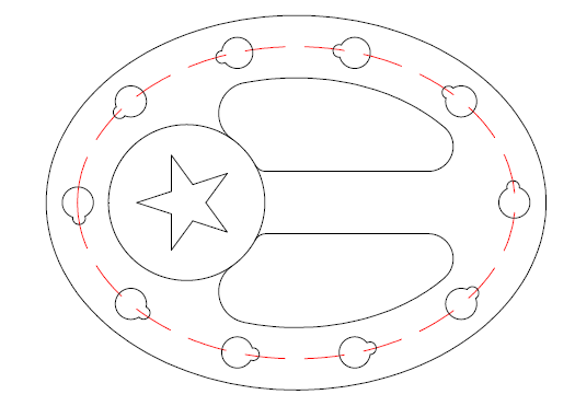
All here is a déjà-vu. Last session, we’ve learned how to use the ELLIPSE command in AutoCAD, in this session we are coming back with an even easier ellipse.
BUT, but now, the focus will be made on something totally different.
in Learn-AutoCAD-DAY-6, we have worked with the ARRAY command for the first time. Today you will need that command line more than EVER. And it is compulsory to have mastered it before trying the coming exercise.
LEARNING AUTOCAD BASICS
NOTE: Element in the array are equally spaced around the ellipse.
hey! If you have any confusion about this, Just leave a comment below. Let me know what is confusing about this, I will make it clear for you
FIGURE 1
FIGURE 2
On the following image, the red line represent the PATH of the array. It resulted of an OFFSET of 5 units from the outer ellipse.
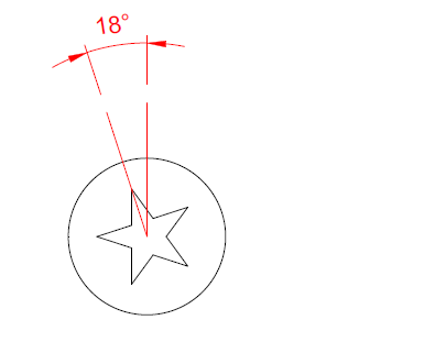
MORE DETAILS ABOUT THE STAR
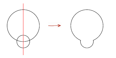
OBJECTS IN THE ARRAY
The object in the array is nothing but the following
You can find dimension of the circles on the first image above.
EXECUTION
The only thing that might be hard to accomplish here is the array. There is nothing like ARRAYELLIPSE in AutoCAD, what you need to do to create this array is using the ARRAYPATH.
To use the ARRAYPATH command using an ELLIPSE, you need to cut the ellipse into two, and use the ARRAYPATH on each of the side, that is it.
We would like to let you fight with it and figure it out yourself, using information we provided above.
Feel free to drop your opinion and concern in the comment section below.
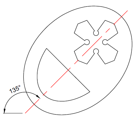
Here is an exiting one! We have just noticed we needed to add more ingredient to our experiment today, for some reasons.
Last DAY, we noticed the exercise we were working on made it too easy to escape the MIRROR command, today, we are coming with one which is meant to make it almost impossible to accomplish without making use of the MIRROR command.
LEARNING AUTOCAD BASICS
FIGURE 1
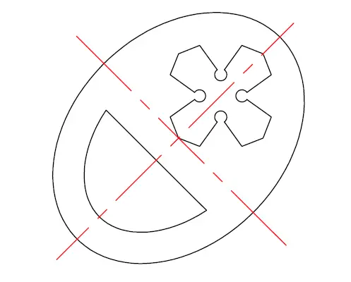
FIGURE 2
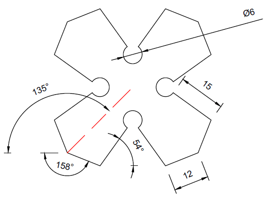
FIGURE 3
The two red lines are both axis of symmetry of the object.
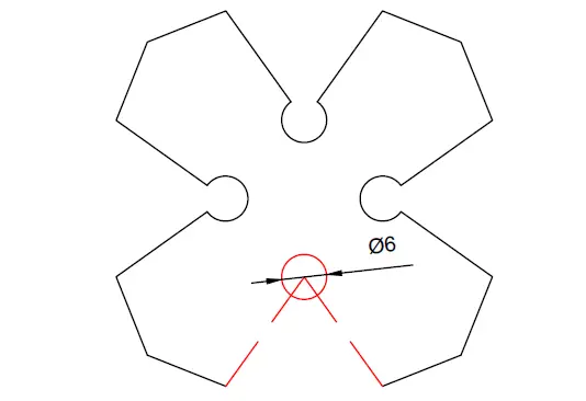
FIGURE 4
Details about the object inside the ellipse.
FIGURE 5
EXECUTION
THE ELLIPSE COMMAND IN AUTOCAD
We will need to use the ELLIPSE command in this session.
To use the ELLIPSE command
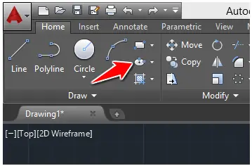
Click on the ELLIPSE icon
Specify the center of the ellipse
Move the cursor in the direction of the first axis, type its value and press Enter
Type the value of the second axis and press Enter
THE POLAR TRACKING
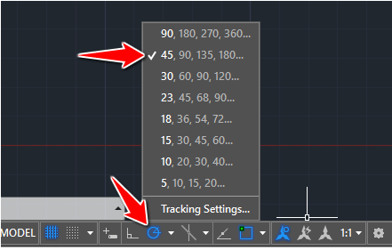
For this experiment, we will make use of the POLAR TRACKING. Activating the following mode of the POLAR TRACKING will contribute to ease our task.
CREATING THE ELLIPSE
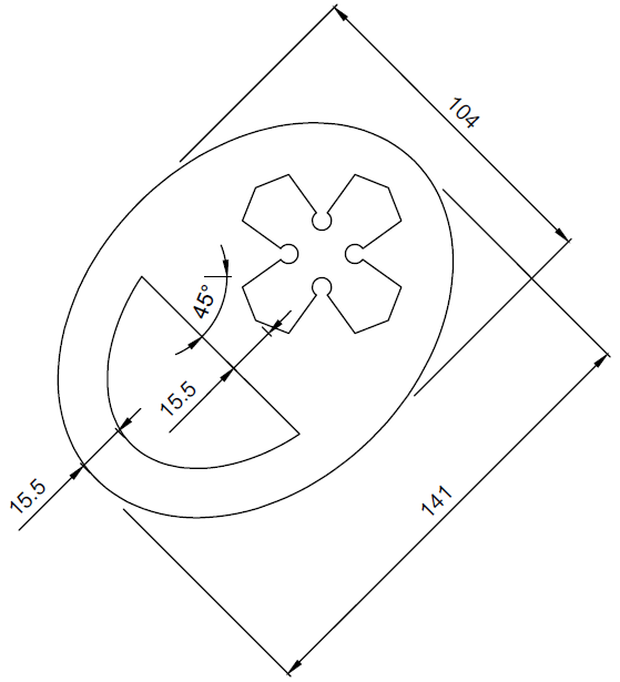
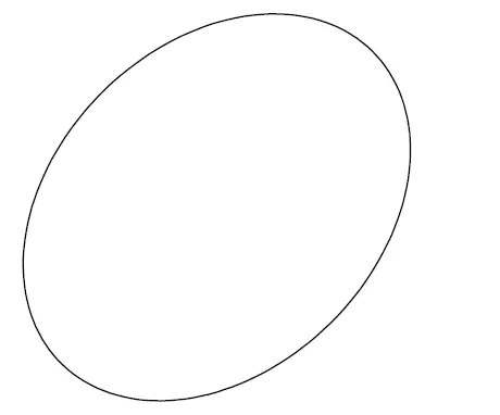
The ellipse is bent with an angle of 45 degrees.
Activate the ELLIPSE command
Specify the center of the Ellipse
Track 45 degrees
Type 70.5 and press ENTER
Type 52 and press ENTER
You should have the following.
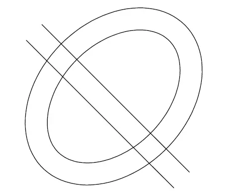
After creating the ellipse all you need to do is find the center line of the ellipse, OFFSET the ellipse and the line with an OFFSET value of 15.5. The resulting image should look similar to the following.
Use the TRIM command to obtain the wanted object.
CREATING THE REMAINING PIECE
To create the cross, you need to:
STEP 1
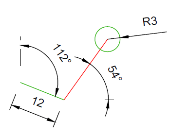
Create the following, you can find the length of the red line using information given earlier.
STEP 2
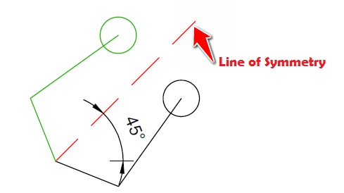
Create a mirrored copy of the current object, the line of symmetry should be a line with and inclination angle of 45 degrees starting from the left end of the drawing.
STEP 3
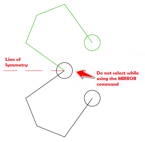
Create a vertical line that will serve as the new line of symmetry. The new line must have an end common with the center of the newly create circle.
You don’t have to select the highlighted circle while you use the MIRROR command.
After obtaining the figure we have just obtained, you can use the same trick to get the other part of the image. And that will be it. Combining both structures should not be an issue.
One of the command we have not been using since the beginning of this series is the MIRROR command. We expect to force its use with today’s session.
Today’s rule will be a bit altered in the sense that we wish you use the MIRROR command. How? If you look closely at the image below you will notice that the object is a sort of symmetric. Imagine a vertical line cutting it into two, both sides will be just identical mirrored copies.
LEARNING AUTOCAD BASICS
Here is the object of today’s experiment.
We’ve said earlier that the object is symmetric, let’s see what a part of it would look like. (The line in red seeing as the line of symmetry)
After removing all FILLET, here is what the image looks like
Here are some information that might be helpful
You can just do the inverse operation to mount that object walking from the last image right above this to the first image we had in the beginning of this session.
We slow down a little today, and we would like you to come back and use some basic commands we think we have not made use of enough.
Now, we are going to look at the CHAMFER command and play with the UCS command a little bit more than we did in the past days.
LEARNING AUTOCAD BASICS
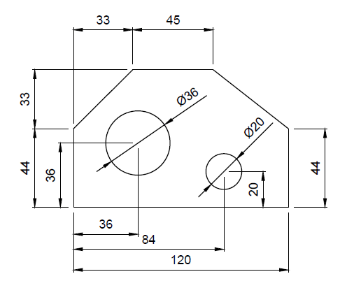
Here is the object we will try replicate in this session, pretty quick one huh!?
We have been into more difficult situation!
EXECUTION
Remember you can do it your own way, but here is how I will suggest you do it.
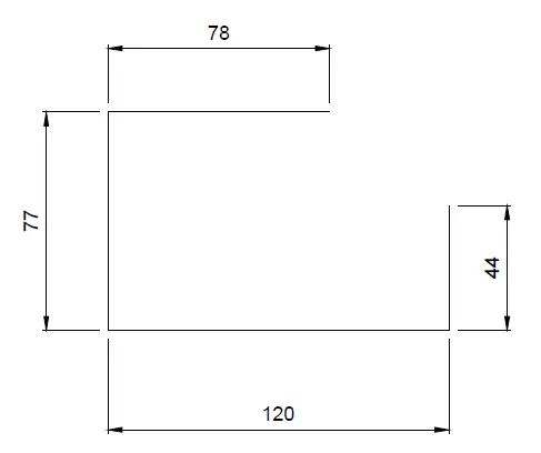
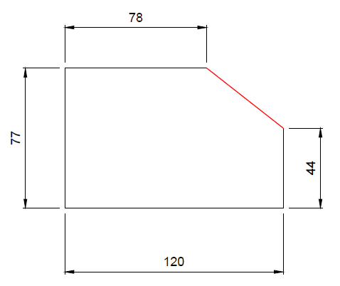
Start with the following. Four lines, you have all dimensions, pretty easy
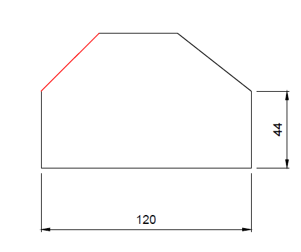
Then, use a line to close the object. You need not to know the length of this line, just use those two points to get it.
Now use the CHAMFER command on the left upper corner. The Chamfer distances are 33 x 33 units.
Learn how to use the CHAMFER command in AutoCAD
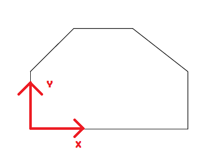
We have made an extensive use of the UCS command earlier. Move the UCS to the position shown on the image below, that will allow you to get the circles we are trying to create at their right positions.
After Getting the UCS at the position shown above, the center of the bigger circle will be at the point of coordinates (36,36) and the center of the small circle will be at the point of coordinates (84,20)
We hope your assessing skill has improved, meaning you are more able to judge the difficulty of an exercise just by looking at it.
In this post, we are going to keep on using basic AutoCAD commands and focus more on how to combine their use to accomplish a specific task.
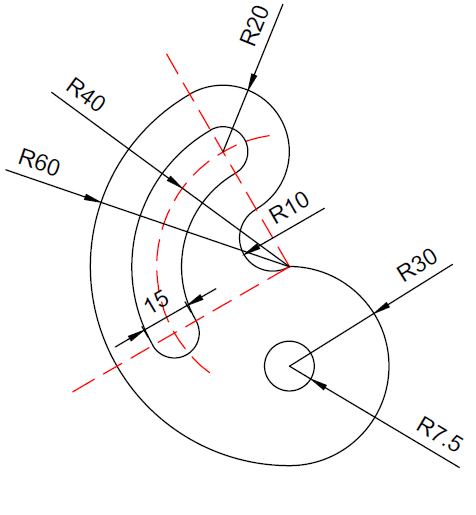
LEARNING AUTOCAD BASICS
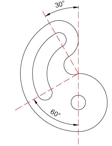
The following are the images we are going to be using today.
FIGURE 1
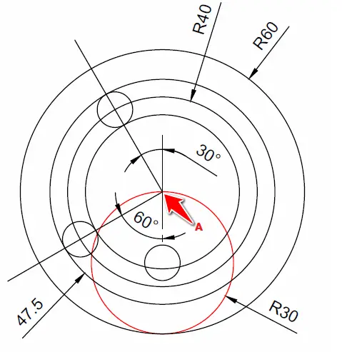
FIGURE 2
EXECUTION
Start by creating the following.
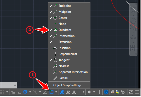
The first object you should create is the red circle. Then make sure the QUADRANT mode is activated in the Object snap settings, this will help you snap the center of those big circles at the point A.
(Right click on 1 and tick 2)
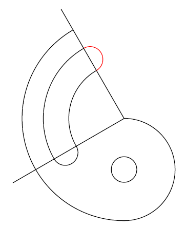
After proper trimming you will end up with the following image
Use the OFFSET command on the red part to obtain the following. OFFSET distance = 12.5 units
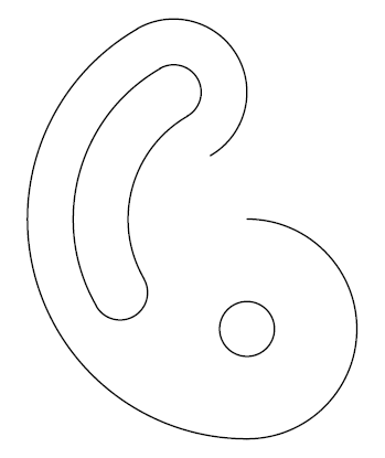
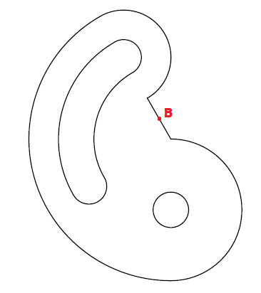
Draw a line from the two openings of the object, and create a circle using the middle point B of the line you have just created.
We have not talked about the small circles 30 and 60 degrees away from the vertical. Using techniques we have used to create objects in previous DAYS, those should not be a problem.