Graphic World

Categories
Articles Learning

Introduction To Auto desk AutoCAD | DAY 17

Learn AutoCAD basics: DAY 17

There is not much hardship in the session we are about to have. This should be a piece of cake if you have been following the series since DAY 1.

Just for the sake of knowing, here are couple of things you need to know before diving into today’s exercise:

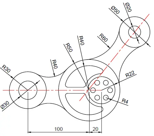
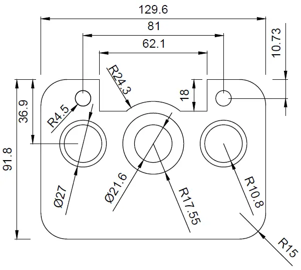
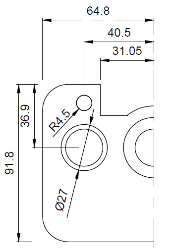
  • You need to have mastered the use of MIRROR command. You can avoid using it but using it the right way to go. After creating those arcs, Use the  MIRROR command to create a mirrored copy on the other side. The red lines can serve as a line of symmetry.
  • To create the arcs, you need to use the feature Tan Tan Radius of the CIRCLE command. If this is the first time you hear about this, it is not late to go and check it out.


LEARN AUTOCAD BASICS

FIGURE 1

learn-AutoCAD-Bacis

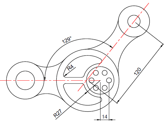
FIGURE 2

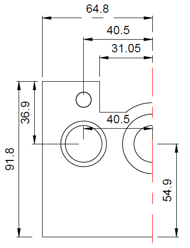
To avoid the preceding image to be too bushy, we’ve split information. You can find the remaining part of the information you need in the following picture.

learn-AutoCAD-Bacis

Categories
Articles Learning

Introduction To Auto desk AutoCAD | DAY 11

Learn AutoCAD basics: DAY 11

Here is an exiting one! We have just noticed we needed to add more ingredient to our experiment today, for some reasons.

Last DAY, we noticed the exercise we were working on made it too easy to escape the MIRROR command, today, we are coming with one which is meant to make it almost impossible to accomplish without making use of the MIRROR command.


LEARNING AUTOCAD BASICS

FIGURE 1
learn-AutoCAD

FIGURE 2

learn-AutoCAD

FIGURE 3

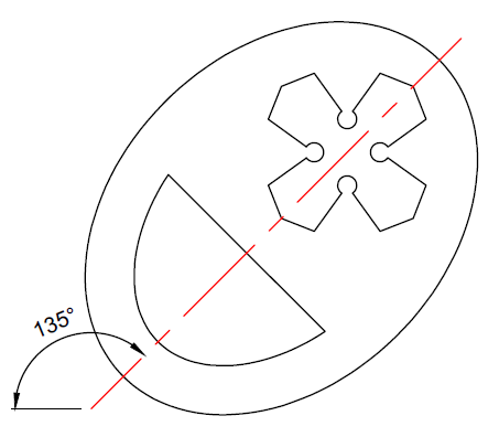
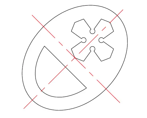
The two red lines are both axis of symmetry of the object.
learn-AutoCAD

FIGURE 4

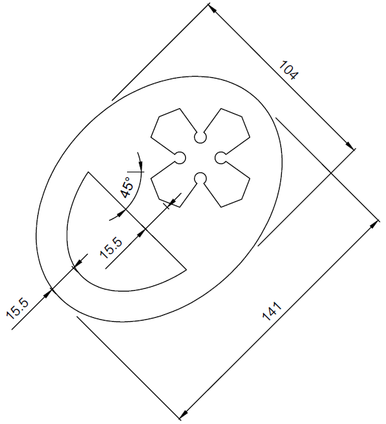
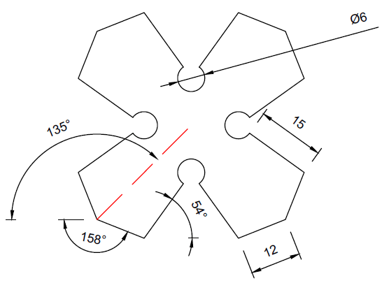
Details about the object inside the ellipse.
learn-AutoCAD

FIGURE 5

learn-AutoCAD

EXECUTION

THE ELLIPSE COMMAND IN AUTOCAD

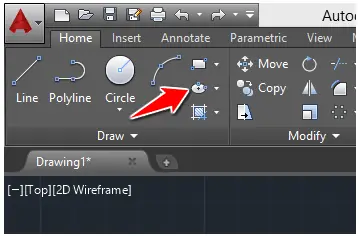
We will need to use the ELLIPSE command in this session.
learn-AutoCAD

To use the ELLIPSE command

  1. Click on the ELLIPSE icon
  2. Specify the center of the ellipse
  3. Move the cursor in the direction of the first axis, type its value and press Enter
  4. Type the value of the second axis and press Enter

THE POLAR TRACKING

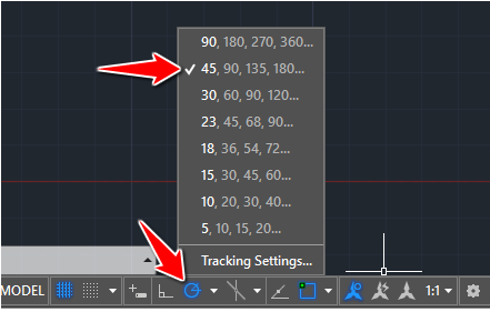
For this experiment, we will make use of the POLAR TRACKING. Activating the following mode of the POLAR TRACKING will contribute to ease our task.
learn-AutoCAD1

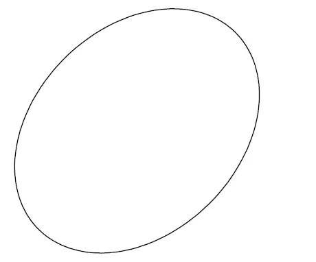
CREATING THE ELLIPSE

The ellipse is bent with an angle of 45 degrees.

  1. Activate the ELLIPSE command
  2. Specify the center of the Ellipse
  3. Track 45 degrees
  4. Type 70.5 and press ENTER
  5. Type 52 and press ENTER

You should have the following.
learn-AutoCAD

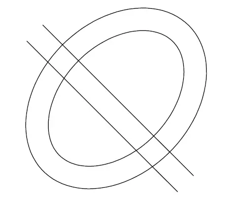
After creating the ellipse all you need to do is find the center line of the ellipse, OFFSET the ellipse and the line with an OFFSET value of 15.5. The resulting image should look similar to the following.
learn-AutoCAD

Use the TRIM command to obtain the wanted object.

CREATING THE REMAINING PIECE

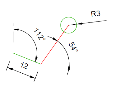
To create the cross, you need to:

STEP 1

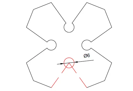
Create the following, you can find the length of the red line using information given earlier.
learn-AutoCAD

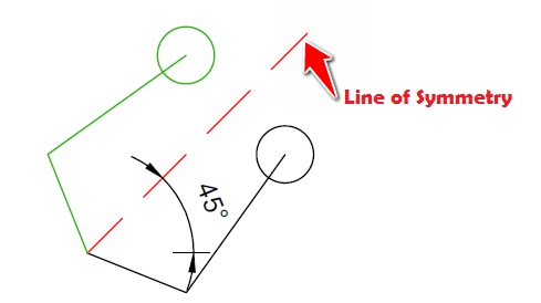
STEP 2

Create a mirrored copy of the current object, the line of symmetry should be a line with and inclination angle of 45 degrees starting from the left end of the drawing.
learn-AutoCAD

STEP 3

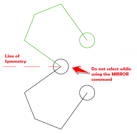
Create a vertical line that will serve as the new line of symmetry. The new line must have an end common with the center of the newly create circle.
learn-AutoCAD

You don’t have to select the highlighted circle while you use the MIRROR command.

After obtaining the figure we have just obtained, you can use the same trick to get the other part of the image. And that will be it. Combining both structures should not be an issue.

Categories
Articles Learning

Introduction To Auto desk AutoCAD | DAY 10

Learn AutoCAD basics: DAY 10

One of the command we have not been using since the beginning of this series is the MIRROR command. We expect to force its use with today’s session.

Today’s rule will be a bit altered in the sense that we wish you use the MIRROR command. How? If you look closely at the image below you will notice that the object is a sort of symmetric. Imagine a vertical line cutting it into two, both sides will be just identical mirrored copies.


LEARNING AUTOCAD BASICS

Here is the object of today’s experiment.

learn-AutoCAD

We’ve said earlier that the object is symmetric, let’s see what a part of it would look like. (The line in red seeing as the line of symmetry)

learn-AutoCAD

After removing all FILLET, here is what the image looks like

learn-AutoCAD

Here are some information that might be helpful

learn-AutoCAD

You can just do the inverse operation to mount that object walking from the last image right above this to the first image we had in the beginning of this session.