

Category: Tutorials


In the field of Architectural Visualization, realism must always be the 1st goal that we strive to accomplish. In this 3 day tutorial series, you will gain a solid introduction to valuable lighting and texture mapping techniques that can be used to achieve realistic architectural renderings.
Additional Files/ Plugins:
Note: click the ‘Monitor’ icon to view tutorial in full-screen HD.

In the field of Architectural Visualization, realism must always be the 1st goal that we strive to accomplish. In this 3 day tutorial series, you will gain a solid introduction to valuable lighting and texture mapping techniques that can be used to achieve realistic architectural renderings.
Additional Files/ Plugins:Note: click the ‘Monitor’ icon to view tutorial in full-screen HD.
Note: click the ‘Monitor’ icon to view tutorial in full-screen HD.
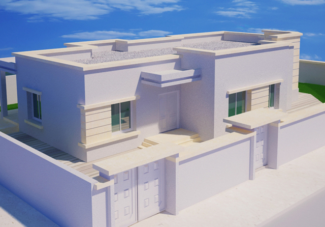
In the field of Architectural Visualization, realism must always be the 1st goal that we strive to accomplish. In this 3 day tutorial series, you will gain a solid introduction to valuable lighting and texture mapping techniques that can be used to achieve realistic architectural renderings.
Additional Files/ Plugins:
- Download the Project Files for this tutorial
- Grass-O-Matic (Free)
Note: click the ‘Monitor’ icon to view tutorial in full-screen HD.
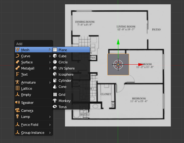
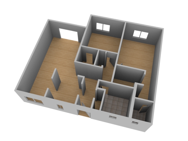
In this tutorial you’ll learn how to create a 3D floor plan model from an 2D architectural drawing. Karan Shah will show you some simple, yet effective techniques for constructing the walls, windows and doors following a basic interior schematic in Blender. With the model complete we’ll add materials and textures, and do a final render of the scene.
Additional Files/ Plugins:

Step 1
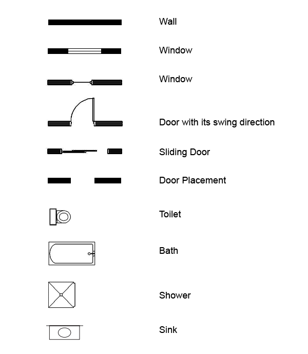
Floor Plans are simply a drawing or a diagram showing a top view of a site layout. You can see the picture to understand the meaning of some basic symbols used. More can be found
here (pdf).
Step 2
In a new file, select all objects with the ‘A’ key and press ‘Del’ to delete them. Press ‘N’ to bring up our View properties. In the Background Image Panel, add your reference image. Here I have used image courtesy ofLiamKeiranCooper Ltd who kept the picture in public domain.

Step 3
Press ‘7’ on the NumPad to get into the Top view. Here you can see the background image. The view must be set to ‘orthographic’ in order to see the image. You can toggle between the ortho and perspective views with the ‘5’ key on the Numpad. Press Shift+A and add a Plane.

Step 4
With the Plane selected, press ‘TAB’ to get into ‘Edit’ mode. Select all the vertices with the ‘A’ key, or press ‘B’ to drag select them. Press ‘G’ and move them to the top left corner. You toggle the viewport shading between solid and wireframe with ‘Z’ key. Press ‘S’ and move the mouse to scale them down to fit the width of the wall (as shown below.)


Step 5
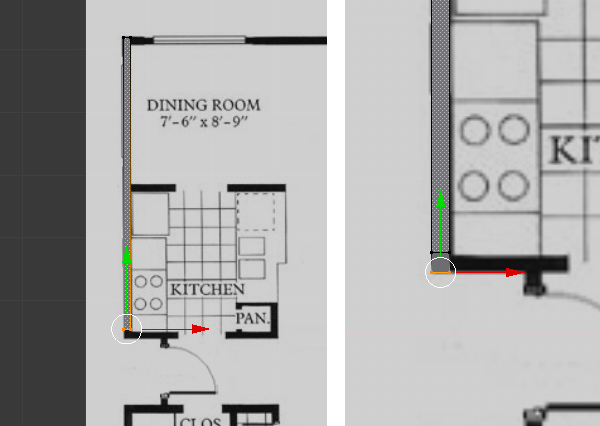
Now we will cover all the black solid areas i.e. the walls. This will include the windows as they are part of the walls and will be added later. Any type of door whether it’s a slider or normal, is to be left out. Select the bottom two vertices (press ‘B’ to drag select or Hold ‘Shift’ and Right click for multiple select.) And move them down just before the wall turns left. Press ‘E’ and extrude the wall again until you reach the edge.
Step 6
Select the right two vertices and press ‘E’ to extrude, and match the reference.

Step 7
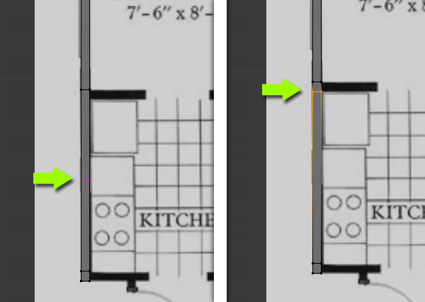
Now, in order to extrude out a face from the middle, we need to add an Edge Loop. Hover your mouse over the face, and press ‘CTRL+R’ and Left Click to confirm. Move the mouse up and down and then Left click again to confirm its position.

Step 8
Create another edge loop just below the previous one using the same method, matching the width of the wall to be extruded.
Step 9
Select the two vertices and extrude the wall.

Step 10
Create another edge loop on the corner and extrude the right edge.

Step 11
Using the techniques above (extrude and edge loop division) fill all the solid black lines of the reference image with the mesh.

Step 12
To start a new separate wall, duplicate the last edge and then start extruding it. Select the last edge and press ‘Shift+D’ to Duplicate it, and left click to confirm. Move it with the Move control widget or press ‘G’ key of the keyboard. And continue extruding the mesh along to match the reference.

Step 13
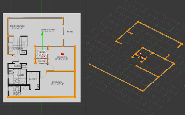
Complete the walls with the techniques you learned from above steps.


Step 14
After completing the wall, select all the vertices and then press ‘E’ to extrude them along the Z axis. Now we see that the structure is taking shape. The height should be equivalent to a door.

Step 15
Press ‘Ctrl+TAB’ and select ‘Edge’ in the mesh select mode menu. Select the top two corner edges of a door (hold shift + right click to multiple select) and press ‘F’ to make a Face between them. Do this for all doors. Refer to your image and always check from all views.


Step 16
Press ‘3’ on the Numpad to get into side view, and Press ‘Z’ to get into wireframe view so that we can see all the vertices behind are visible and can be selected. Press ‘B’ to drag select all the top vertices or edges, then Press ‘E’ to extrude them. This will reach the final height of the wall.


Step 17
Now we will place the windows. Press ‘TAB’ to get out of the Edit mode, and in object mode, press ‘Shift+A’ and add a ‘Cube’. In the Top view, size (press ‘S’ to scale) and place it where the window is on the reference image.

In the side view, the top part of window should align to the top of door. Press ‘TAB’ to enter into the edit mode to adjust the vertices. Adjust the bottom height of the window too. The width of the cube should be such that it should be half inside and half outside. See image below.

Step 18
Select the Wall mesh with Right click, and in the Properties button window, click on ‘Object Modifiers’.

Click on ‘Add Modifiers’ and select ‘Boolean’.

Step 19
In the Boolean modifiers panel, select ‘Cube’ in the Object, and ‘Difference’ under ‘Operation’.

To see the effect – Select the cube and press ‘H’ to hide it. You will see that there is a “hole” in the wall the size and shape of the cube. Press ‘Alt+H’ to ‘Unhide’ the Cube.

Step 20
Now select the Cube (window) and in the ‘Edit’ mode, select all the vertices and press ‘Shift+D’ to make a duplicate. Place this new cube in the location of the next window.
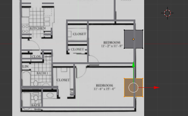
Now press ‘Tab’ to get out of ‘Edit’ mode, and select the Wall mesh and press ‘Apply’ in the ‘Boolean’ Modifier panel. The holes are now part of the geometry.
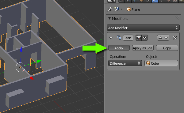
Move the Cube to see the windows.

Step 21
Similarly create all the needed windows with this Boolean modifier. Try doing them one by one, adjust the size and position of the cube according to the specific window.
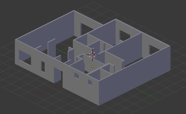
Step 22
Now we will create the Floor. In ‘Object’ mode and in the Top view, press ‘Shift+A’ and add a ‘Plane’. Press ‘Tab’ to get into ‘Edit’ mode and adjust the vertices accordingly so that it covers the walls. Create Edge Loops or Extrude the edges where necessary.


Step 23
Make sure that there are no gaps between the edges of the floor and walls. Also in the Side view, move the floor down so it’s aligned with the bottom of the walls.

Step 24
To make doors, add a new’Cube’. And in ‘Edit’ mode, press / on the Numpad for Local view (this will show only the selected object.) In the Top view, Move or Scale the vertices to give it a nice shape. Refer to the image for the height and width.

In the Top view, and in ‘Edit’ mode. Move all the vertices of the door along the Y axis, so that the center point of the object (orange dot) should be at the corner (see image.) This will set the transform orientation of the object from that corner. Press ‘TAB’ to get out of edit mode and then press’R’ to Rotate and see the difference.

Step 25
While in the edit mode, add a new ‘Cylinder’. Rotate and scale it down to create the doorknob (you can add more details if you like.) Press ‘TAB’ to get out of edit mode.

Step 26
With the help of the reference image, place the doors in the correct positions (press ‘Shift+D’ to make duplicates.)

Step 27
Now we will create the window frame. Start with another new ‘Cube’, and press ‘TAB’ to enter into ‘Edit’ mode. Press the ‘Z’ key to toggle wireframe view, so that we can select the back vertices too. Press ‘3’ on the Numpad to get into side view and then extrude the faces as shown in the image to make the window frame. Press ‘TAB’ to exit out of edit mode, and press / on the numpad again to get back to the scene.

Step 28
Scale and place the window frames on the walls. Make duplicates and place them according to the image.

Step 29
Now we will add a texture to the floor. Right Click on the Floor object to select it. And in the Properties window, click on the ‘Materials’ Icon. Add a New material and name it ‘Floor’, increase the ‘Diffuse’ intensity and reduce the ‘Specular’ intensity.

Step 30
Next we will add an image to the floor. (I got mine from Here.) Click on the ‘Texture’ icon next to the Material icon, and then Click on the ‘New’ button. Select ‘Image or Movie’ for the Type and in the Image panel, click on “Open’ and browse for the image.

Step 31
You can preview the texture in the 3d View. Press ‘N’ to bring up the ‘View Properties’ and in the ‘Display’ panel, select GLSL in the ‘Shading” menu (you’ll need to add some lights in the 3d view to see the texture.) Now press ‘N’ again to hide the view properties panel.

Back to the Image Texture properties, scroll down to the Mapping Panel and increase the Size of X and Y to5 or 6 depending upon your image file.

Step 32
Now to add a separate floor to the Bathrooms, we will add a new ‘Plane’ and adjust it’s dimensions and place it just above the wooden floor so that it’s hidden.

Apply an image, just like we did on the floor (I got mine from Here.) Duplicate the Plane and adjust it’s geometry by scaling and extruding for the second bathroom.


Step 33
Select the walls and add a New material to them. Choose any color and Increase the ‘Diffuse’ intensity and set the ‘Specular’ to 0.0

Similarly assign the materials to the windows and doors. You can assign the same material to any object by selecting the material from the list.

Step 34
Now we will prepare the scene for rendering. Make sure you are Not in ‘Edit’ mode (press ‘TAB’ to toggle Edit mode on/off.) Press ‘7’ on the Numpad to get into the Top view, then press ‘Shift+A’ to add a camera.

Rotate and place it however you like. Press ‘0’ on the Numpad to get into camera view.
Step 35
Click on the ‘World’ settings and change the ‘Horizon Colour’ to white, then turn on ‘Ambient Occlusion’ and in the ‘Gather’ panel, increase the samples to 16. In the 3D view delete any lights if they exists.

Step 36
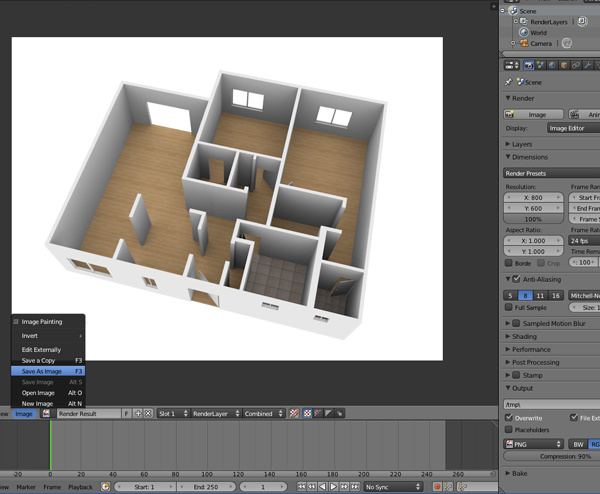
Click on the ‘Render Settings’ button in the property window, and change the Dimensions (resolution) to your desired size. Down in the ‘Output’ panel, choose the file format for your render.

Press ‘F12’ or click on the ‘Image’ button in the render panel. Press ‘F3’ or click on ‘Image > Save image as‘ to save the image.
Your 3D Floor map is now ready!
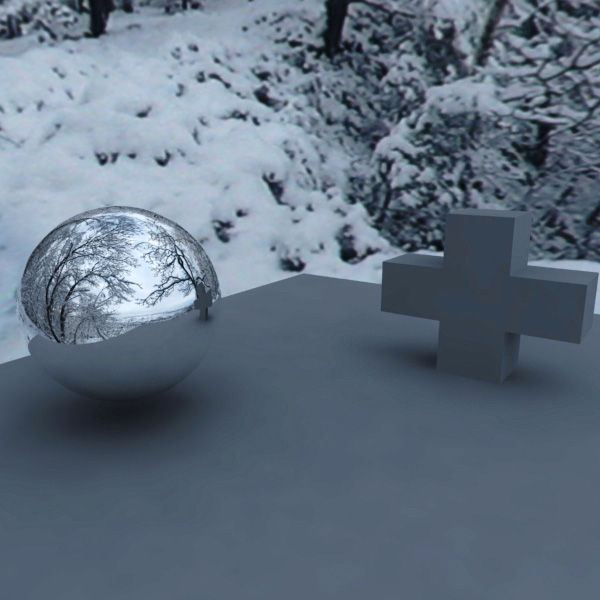
In today’s Quick-tip tutorial, Edgar Mihailov shows artists new to Maya, and/or it’s relatively new Vray plugin, how to utilise High Dynamic Range Images (HDRIs) to illuminate your scenes, providing realistic reflections in the process. HDRI is now a standard across almost all rendering software and it’s an extremely useful thing to learn how to use!
Hi everyone! In this tutorial I will be showing you how to first enable Global Illumination (GI) within your scene, and then we’ll add an HDRi map using Vray for Maya. I will be using Maya 2011, but the process is extremely similar in some of the older versions of Maya (up to a point of course!) This tutorial is intended for people who are new to Vray itself, or just the Vray for Maya plugin.
I can’t actually share the HDR image I use in the tutorial, however there are a reat many places on the web where you can download free HDRIs to use in your scenes (though please always be aware of commercial restrictions.) A great website for free HDRi maps is http://www.openfootage.net/, but I would advise you to buy at least one good HDRi map pack, as they are typically of higher quality and allow you to achieve the results below in your commercial projects.
Step 1
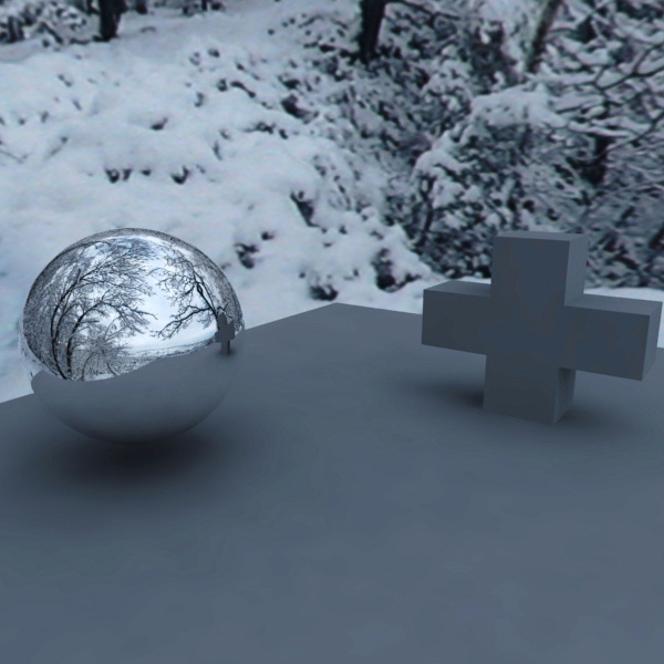
For the purpose of this tutorial I made this very simple scene. It’s essentially just a sphere, a plane for the floor, and a cross shape (which is nothing more than an extruded cube). Although simple, this will be more than enough to allow us to correctly set up our HDRI, and clearly see the results.

Step 2
Before we can start we first have to make sure that the Vray plugin is loaded. To do this, click Window on the top menu bar, and then hover your cursor over Settings/Preferences and a menu will pop up. Once it’s opened, choose the very bottom Plug-in Manager.

Step 3
Maya’s Plugin Manager menu will appear. Scroll all the way down to the bottom and make sure thatvrayformaya.mll is checked as Loaded. If you do a lot of work with Vray, you might want to check Auto-loadas well, which will make the plugin load up everytime Maya starts.
Note : If you don’t see a vrayformaya.mll entry in the list, make sure you have installed the plugin correctly. If you reinstall the plugin, make sure you restart Maya before re-checking the Plugin Manager.

Step 4
Now we have to switch our rendering engine to Vray. To do so, switch to the Rendering menu-set (by using the dropdown menu underneath the File and Edit menus on the top bar), then go to Render > Render Using > V-Ray.
Note: You can also see here the other renderers you have access to on the system. By default, Maya comes with Maya Software, Maya Hardware, Maya Vector and Mental Ray – all of which are covered heavily in the documentation.

Step 5
After that is done we have to go in and set up our materials. Go to Window > Rendering Editors > Hypershade to open Maya’s main material editor/creator.

Step 6
In the image below you can see the Hypershade. On the right are the 3 existing material nodes in the scene, and on the left is a list of all of the material nodes you can create. We want to create a standard Vray material, so click twice where it says “VRay Mtl” to create two materials. As you do this, the new materials will pop up in the right hand side of the Hypershade. For this tutorial only these two materials will be needed.

Step 7
Now double-click on one of the materials that we just created to open up the Attribute Editor. (This may appear as a floating panel, or docked to the right hand side of the main window.) In the Attribute Editor go to the Reflection section and change the Reflection Color to white by sliding the slider all the way to the right. This makes the material fully reflective – it is essentially now a mirror. We don’t need to alter the other material as the standard settings will do for this test. Whilst I won’t name the materials here, I strongly advise you to give each material a descriptive name if you’re putting together a complex scene.
Note : If the Attribute Editor doesn’t open, click once on your new material and hit CTRL+A to open it.

Step 8
To apply our new materials to our objects, hover your cursor over the material in the right side of theHypershade, hold down the middle mouse button, move your mouse over the object you want to apply your material to, and then release to apply it. Using this method, I applied our mirror material to the sphere object, and the other default grey material to the floor plane and the cross object.

Step 9
Now we have to change our render settings and add in our HDRI. To do this, go to Window > Rendering Editors > Render Settings

Step 10
We’re now going to enable Global Illumination, a key part of making the HDRI work as it allows us to take into account any light coming from our environment within the scene. Switch to the Indirect Illuminationtab and make sure that the first check box is turned on to enable GI. For this simple test I’ll leave the rest of the settings at their default values, but you should feel free to experiment. For instance, the Primary Bounces Multiplier can be increased to brighten up a dark scene, which can be useful for some HDR images.

Step 11
In order to use an HDRi map for our overall lighting, we have to switch to the VRay tab and tick Override Environment. If we were to do a test render now, the scene would be a light blue color instead of pitch black. That blue color is coming from the GI texture swatch as shown in the image below. This is where we’re going to need to add in our HDRI.

Step 12
Before we can do that however, we have to create a material for our HDRi map. So head back into theHypershade (Window > Rendering Editors > Hypershade) and click the Textures tab as shown at 1 in the below image. We need to create a File texture to load in our HDRI, but it might not be easy to find in the list of available materials/textures. To speed up this process, type File into the search bar shown at 2 in the below image. This will quickly allow you to find a specific texture node. Once done, click once on the Filenode shown at 3 – it should appear in the right hand side of the Hypershade.
If you have stuff in your “Work Area”, click the eraser icon to clear it.

Step 13
Click once on the new File node to select it and hit CTRL+A to bring back the Attribute Editor. Once there, click on the folder icon next to Image Name and navigate to/select your HDRI map. It might take a while to load depending on the speed of your computer and size of the map.

Step 14
Now open both the Render Settings window and the Hypershade window side-by-side. Just like when we applied the materials to our objects, we need to hover over the HDRI File node in the Hypershade, hold down the middle mouse button, move the mouse over to the black swatch next to Background Texture and then release. Maya will automatically add the File texture into this slot for us. We now need to repeat this process for the GI texture, Reflection texture and Refraction texture slots.
Note: Ideally you should use a low-res, slightly blurred version of your HDRI in the GI Texture slot, as it provides much smoother lighting throughout the scene. The 3 other slots should all use the high-res version.

Step 15
You may notice that you can now see your image in the main viewport. If it looks as expected feel free to skip this step, however if your HDRi map is rotated sideways you may need to do the following…
Go back to the Render Settings, and in the Environment tab click where it says Edit UV Placement. As all of our maps are using the same file, altering one UV Placement affects all of the maps, however if you’re using multiple maps you would need to repeat this fix for each one of them.
In the Attribute Editor, change the Vertical rotation from 0 to 90, which will rotate our image map 90 degrees, hopefully lining it up straight! If it’s still not straight, feel free to change the number until it looks correct.

Step 16
Our materials and HDRI are now all in place so it’s time to render! From the top menu, go to Render > Render Current Frame.

Step 17
Once completed, your render should look something like this. Now go and experiment with different HDRIs to see the wide range of results you can achieve! If you have any questions feel free to leave them below. Thanks!


1. Creating a Basic Scene
Step 1
Open 3ds Max.

Step 2
I have made a simple scene. I have put three objects with some distance between each other.

Step 3
Press Ctrl-C to create a camera in the perspective view.

2. Set Object ID
Step 1
With the teapot selected, do a right click and select Object Properties.

Step 2
It opens the Object Properties window. Set the Object ID value as 1.

Step 3
Following the same way, set the Object ID value of the cylinder as 2.

Step 4
Following the same way, set the Object ID value of the box as 3.

3. Rendering in RPF Format
Step 1
Press Shift-Q or F9 key to render the scene.

Step 2
Click on Save Image icon. It opens the Save Image window. Set the file name as Diffuse and select the file format as RPF. Click on Save button.

Step 3
It opens the RPF Image File Format window. Choose 16 Bits per channels option. Turn on all options. Click on OK button.

4. Compositing in After Effects
Step 1
Open After Effects. Import the Diffuse.RPF file in the timeline. You will notice the file has come with all properties like Z-depth, Object ID, Z–coverage etc.

Step 2
With the Diffuse.RPF layer selected, go to Effects > 3D Channel > ID Matte.

Step 3
In ID Matte effect, the default value of ID Selection is set to 0.

Step 4
Set the ID Selection value as 1. You will see that only the teapot is visible. This happens because in 3ds Max, I had set the object id value of the teapot as 1.

Step 5
Make the duplicate layer of Diffuse.RPF layer by pressing Ctrl-D key.
This time, set the ID Selection value to 2. The cylinder gets highlighted, because in 3ds Max, I had set the object id of the cylinder as 2.

Step 6
Once again, make the duplicate layer of Diffuse.RPF layer by pressing Ctrl-D key. This time, set the ID Selection value to 3. The box gets highlighted also, because in 3ds Max, I had set the object id of the box as 3.

Step 7
You can give proper name to the layers as Teapot, Cylinder and Box. Bring the diffuse layer once more in the background to get the floor.

Step 8
Now you can control the individual layer. For example, if you want to change the color of the teapot, just select the teapot layer, go to Effect > Color Correction > Hue/Saturation.

Step 9
Change the Master Hue value and you will see the color of the teapot changes accordingly.

Step 10
Following the same way, you can apply Glow to the cylinder layer. This way, you can control any layer individually and apply any effect.

5. Z Depth Compositing in After Effects
Step 1
With the diffuse layer selected, go to Effect > 3D Channel > 3D Channel Extract.

Step 2
With Z Depth channel selected, it looks like as shown in the following image.

Step 3
You can play with the Black and White values to get the perfect Z depth. Just remember that the nearest object to the camera remains in white and as it travels far, it becomes grey.

Step 4
With the layer selected, press Ctrl-Shift-C to pre compose. Rename the pre composed layer as Diffuse.rpfComp 1.

Step 5
Bring the Diffuse layer in the timeline. Turn off the pre composed layer.

Step 6
Apply S_Z Blur effect on the Diffuse layer. Alternatively you can use Camera Lens Blur. It makes the entire layer blurred.

Step 7
Pick the pre composed layer as the Z Buffer channel. Now you get the real depth of field in the image. The front teapot looks in the focus while the cylinder and box look out of focus.

Conclusion
In this tutorial, I showed you how to control the individual object in the layer by using just one pass. This is the beauty of RPF file format. It contains almost every channel like Z Depth, Object ID, Material ID, Z Coverage etc and every channel could be controlled by using just one layer.
In the next part of the tutorial, I will show you the most useful and powerful file format used in the industry to control everything.


1. Creating a Basic Scene
Step 1
Open 3ds Max. Draw a plane in the perspective viewport.

Step 2
Make a teapot and put it on the plane.

Step 3
I’ve applied several lights in the scene. I’ve chosen Ray Traced Shadows as the shadow.

Step 4
Press M to open the Material Editor. Select an empty slot. Click on Reflection channel.
It opens the Material/ Map Browser. Select Raytrace and click on OK.

Step 5
Apply this material to the plane.

Step 6
Increase the Specular level and Glossiness of the teapot.

Step 7
Render the scene. You get one rendered frame. In this rendered frame, you get Diffuse Color, Shadow,Specularity and Reflection.
Right now, you can’t control individual channel. It will affect the entire frame. You’ll need to render each and every pass separately.

2. Multi Pass Rendering in 3ds Max
Step 1
Press F10 to open Render Settings window. Click on Render Elements tab.

Step 2
Click on Add button. It opens Render Elements window. Select Diffuse and click on OK.

Step 3
Following the same way, click on Add button and add Reflection, Shadow and Specular.

Step 4
You have successfully added these 4 passes in the Render Element list.

Step 5
With Diffuse pass selected, click on Browse tab.

Step 6
Save the file as Diffuse.TGA.

Step 7
It opens Targa Image Control window. Choose 32 Bits-Per-Channel option. Click on OK.

Step 8
Following the same way, save the Reflection, Shadow and Specular files in TGA format.

Step 9
Click on Render button.

Step 10
You will get 4 different rendered frames for each individual pass.

Step 11
This is Diffuse pass.

This is Reflection pass.

This is Shadow pass.

This is Specular pass.

3. Compositing in After Effects
Step 1
Open After Effects.

Step 2
Import all passes inside After Effects and put them on the timeline in order.

Step 3
To get all passes at the right place, you need to put them in order. Keep the order of the passes as shown in the following image. With the Reflection pass selected, change its blending mode to Screen.

Step 4
Now you get the final composited scene.

Step 5
The beauty of this process is that, you can control each individual pass separately. If you want your shadow a bit light, you can decrease the Opacity value of the Shadow layer, and it will affect the shadow only. All other layers/ passes will be unaffected.

Step 6
If you want to make the reflection blurred, just apply Gaussian Blur effect to the Reflection layer. Play with the blur value, and it will affect the reflection only.

Conclusion
Multi pass rendering and compositing is a great time saver technique. It not only saves the time, but also enables the compositor to work more efficiently and independently on the compositions.
In the next part of the tutorial series, I’ll show you some more important passes in 3ds Max, RLA, RPF andOpen EXR format which make the compositing process even much better.

Preview
1. Creating the Chain
Step 1
Open 3ds Max. Go to Shapes > Splines > Ellipse and draw an oval shape in the front viewport.

Step 2
With the oval shape selected, open the Rendering rollout tab. Turn on Enable In Renderer and Enable In Viewport options. Increase the Thickness value to 7.

Step 3
Right click on the oval shape and turn it into Editable Poly.

Step 4
With the oval poly shape selected, click on Hierarchy panel. Enable Affect Pivot Only option and drag the pivot of the oval poly shape to the extreme right.
Don’t forget to turn off the Affect Pivot Only option after that.

Step 5
Make a copy of the oval poly shape and rotate it. Both objects must not intersect each other.

Step 6
Make several copies of the oval shapes to form a chain link.

2. Creating Constraint
Step 1
With the chain selected, go to Mass FX toolbar and select Set Selected as Dynamic Rigid Body option.

Step 2
With the first oval poly shape from the left side selected, go to Constrains > Create Universal Constraint.

Step 3
It creates a UConstraint at the pivot point of the oval poly shape.

Step 4
For the first oval poly object, its parent would be the next oval poly object.
Click on Parent tab and select the next oval poly object as the parent of the first oval poly object. Turn onFree radio buttons of Swing Y, Swing Z and Twist properties.

Step 5
You can lower the UConstraint icon size also. Put a smaller value in Icon Size.

Step 6
Following the same way, with the next oval poly object selected, go to Constraints > Create Universal Constraint.

Step 7
It creates a UConstraint at the pivot point of the oval poly shape.

Step 8
For this oval poly object, its parent would be the next oval poly object. So, click on Parent tab and select the next oval poly object as the parent of the selected oval poly object. Turn on Free radio buttons of Swing Y, Swing Z and Twist properties.

Step 9
Following the same way, keep making constraints for each oval poly object one by one. After a couple of minutes, you will have the completed chain.

Step 10
Create a sphere. Put it at the end of the chain link. This will act as the wrecking ball.

Step 11
Put the pivot of the sphere at the edge of the sphere as shown in the following image.

Step 12
Make this sphere as a dynamic rigid body.

Step 13
Apply Universal Constraint to the sphere.

Step 14
For this sphere object, its parent would be the first oval poly object. Click on Parent tab and select the first oval poly object as the parent of the selected sphere object. Turn on Free radio buttons of Swing Y, Swing Z and Twist properties.

Step 15
Create a small low poly sphere at the extreme right end of the chain.

Step 16
This time, make this sphere as a Kinematic Rigid Body.

Step 17
With the indicated oval poly object selected, apply Universal Constraint to it.

Step 18
Select the low poly sphere as the parent of it. Turn on Free radio buttons of Swing Y and Swing Z. Keep the radio button of Twist turned off.

Step 19
With the wrecking ball sphere selected, click on Mass FX Tool icon. Inside the Mass FX Tool window, go toMulti-Object Editor tab and put the Mass value as 5.

Step 20
Click on Start Simulation icon. You will see a fine simulation of chained wrecking ball in the viewport.

3. Installing Fracture Voronoi Script
Step 1
Go to scriptspot.com and download Fracture Voronoi script.

Step 2
Save the script in the 3ds Max Scripts folder.

4. Fracture the Wall
Step 1
Create a box in the viewport to make a wall.

Step 2
With the wall selected, go to Max Script > Run Script.

Step 3
It opens the Choose Editor file window. Select the Fracture Voronoi script and click on Open.

Step 4
It opens the Fracture Voronoi script window. Click on Pick Object button and then select the wall in the viewport.

Step 5
I have set the Nb parts as 40 since I want the wall to be broken into forty different chunks. I’ve selected theUniform color option as I want all the chunks in a same color.

Step 6
Click on Break in 40 button. It breaks the box wall into 40 pieces.

Step 7
You can further break each broken piece into several more chunks. Select a broken piece and then repeat the process from Steps 2 to 6.

5. Fracture Simulation
Step 1
With all wall chunks selected, make them as Dynamic Rigid Body.

Step 2
With all wall chunks selected, go to Multi-Object Editor tab and put the Mass value as 5. Turn on Start in Sleep Mode option.

Step 3
Click on Start Simulation button. You will see the wall shattering simulation in the viewport.

Step 4
Once you are satisfied with the simulation result, click on Bake All tab to bake all simulation.

Conclusion
Mass FX is a great dynamics tool in 3ds Max. It has replaced Reactor and has more controls over the dynamic simulation than ever.

I’ll show you how to render it as a separate pass so that you can control its intensity in multi pass compositing easily.
The Result
1. Preparing the Scene
Step 1
Open 3ds Max. Open the smart_phone.max file which has been provided with the tutorial.

Step 2
- Press M to open the Material Editor. Select an empty material slot.
- Click on Diffuse channel. It opens the Material/ Map Browser window.
- Select Bitmap and click on OK.

Step 3
Select screen.jpg image. This will be used as the texture of the mobile screen.

Step 4
I have used several omni lights in the scene.

Step 5
Press Shift-Q or F9 to render the frame. This looks good but there is no reflective sheen on the screen right now.

2. Creating the Reflective Sheen
Step 1
Create a plane with the length and width as 200 and 80 respectively.

Step 2
Put this plane in front of the mobile phone as shown in the following image.

Step 3
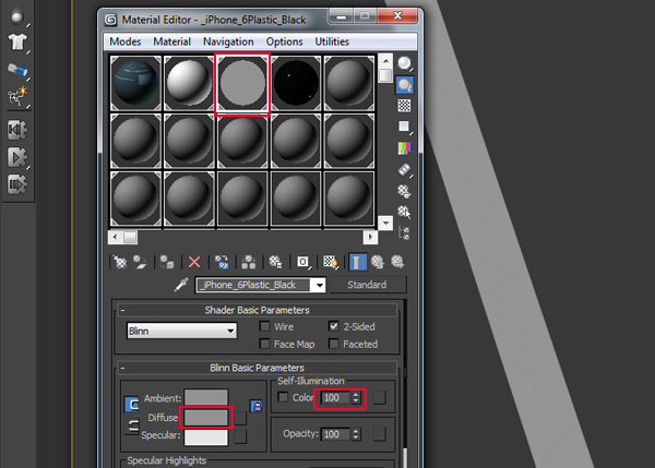
- Press M to open the Material Editor
- Select an empty material slot
- Set the Diffuse color as grey
- Increase the Self-Illumination level to 100%
- Apply this material onto the plane
Step 4
With the screen material slot selected, click on Reflection channel.

Step 5
It opens the Material/Map Browser window. Select Raytrace and click on OK.

Step 6
With the plane selected, do right click and select Object Properties.

Step 7
It opens the Object Properties window. Turn off Visible to Camera option. Click on OK.

Step 8
Press Shift-Q or F9 to render the frame.
This time you get the sharp reflective sheen on the mobile phone’s screen. The reflective plane is there but you don’t see in the rendered frame because you have turned off Visible to Camera option.

3. Reflective Sheen Pass Rendering for Compositing
Step 1
If you want to control the visibility or intensity of the reflective sheen, you need to render it as a separate pass, so that you can control it later in the compositing software.

Step 2
Press F10 to open the Render Setting window. Click on Render Element tab.

Step 3
Click on Add button. Select Diffuse, Lighting and Reflection. Click on OK.

Step 4
Click on Render button.

Step 5
You get three different passes as Diffuse, Lighting and Reflection. Save each of them in the TGA file format.

4. Compositing in After Effects
Step 1
Open After Effects.

Step 2
Import all 3 passes one by one and put them in order on the timeline.

Step 3
Put Reflection layer on the top of the Diffuse layer. It looks dark.

Change the blending mode of the Reflection layer to Add. Now you get the reflective sheen on the screen. Since this reflective sheen pass is a separate layer so you can easily control it without affecting any other layer.

Conclusion
Reflective sheen pass adds beauty to the final output. There is quite an easy set up for it. If you use it as a separate pass, you can control it quite easily in post production software.

Although the most popular pipeline to track a live action scene is to work in a dedicated 3d tracking system like Boujou, PF Track, Syntheyes and then export the camera to 3d application.
Not everyone, however, can afford these costly 3d tracking systems. For those, who have limited resources, they still can track the scene in After Effects and then export the tracking data to 3d application.
In this tutorial, I will show how to track a live action scene in After Effects and then exporting the camera data to 3ds Max.
1. Project Setting
Step 1
Open After Effects.

Step 2
Go to Composition > New Composition to make a new composition.
Alternatively, you can press Ctrl-N keys. It opens the Composition Settings window.
Set the Width and Height values to 1280 and 720 respectively.
Set the Frame Rate to 25 and Duration to 12 seconds. Click on OK.

Step 3
Go to File > Import > File to import the image sequence. Alternatively, you can press Ctrl-I keys. With the first image of the image sequence selected, turn on JPEG Sequence option. Click on Open.

Step 4
With the image sequence selected in the Project window, press Alt-Ctrl-G keys to open the Interpret Footage window. In the Interpret Footage window, set the frame rate to 25 and click on OK.

Step 5
With the image sequence selected, drag and drop it inside the composition. You can see the footage in the comp view.

2. Camera Tracking in After Effects
Step 1
With the image sequence layer selected, go to Animation > Track Camera.

Step 2
The 3D camera tracker system starts analysing the footage. It analyses the footage in two steps.

Step 3
After a couple of seconds, the analyse process ends. Now you can see several track points in the scene.
If the track points are too tiny, you can increase the value of Track Point Size in the 3D Camera Trackereffect.

Step 4
These track points would help to generate the dummy 3D plane/null and the camera. You need to select at least four points to generate the helping dummy or layer.
Select several track points on the ground as shown in the following image.

Step 5
With the points selected, secondary-click the mouse and select Create Null and Camera.

Step 6
You get a null object and 3D camera in the timeline. This null object is the placeholder and sticks with the footage and follows the camera.

3. Exporting Camera Data to 3ds Max
Step 1
Go to www.aenhancer.com and you will find that they have released a free script AE3D for After Effects. You can download the script from there.
Alternatively, the script has been supplied with the tutorial also. Just copy the script and paste it in theScript folder of After Effects.

Step 2
Restart After Effects. Open the same composition again.
With the null object and 3d camera layers selected, go to File > Script > AE3D_Export.jsx.

Step 3
In the AE3D window, select the 3ds Max option, set the file name to camera tracker.ms and then click onExport. It saves the 3ds max script file on the desktop.

4. Creating Scene in 3ds Max
Step 1
Open 3ds Max.

Step 2
Go to MAXScript > Run Script.

Step 3
Here select the camera track.ms script which was exported from After Effects. Click on Open.

Step 4
You get a 3d camera and one dummy in the scene.

Step 5
In the perspective view, press C key for the camera view.

Step 6
Right now the camera is upside down. You need to correct the coordinate of camera.

Step 7
With the camera and dummy selected, group them together.

Step 8
After grouping, jump in the left viewport. Select the Rotate tool and rotate it to the right side. Your goal should be to put the dummy on the grid line.

Step 9
Adjust the dummy a little bit more to make it straight.

Step 10
Jump in the camera view. Press Alt-B keys to open the Viewport Configuration window. Turn on Use Filesand Animate Background options. Click on Files.

Step 11
Select the image, turn on Sequence option and click on Open.

Step 12
Turn on the Show Safe Frame option in the camera view.
Alternatively, you can press Shift-F keys.

Step 13
You can now make any 3d model and put it on the grid around the dummy. In my case, I have made a barrel model which I have imported into the scene.

Step 14
At this stage, if you render the complete scene and play the video, you’ll notice sliding problem in the 3d object.
To overcome this problem, drag the grouped dummy and camera a bit down. You should put the dummy at half of the black grid line.

Step 15
Put a plane beneath the 3d barrel. Apply Matte Shadow on to the plane.

Step 16
Apply a Skylight in the scene. Turn on Cast Shadow option.

Step 17
Render the frame and you will see the 3d barrel is perfectly merged with the scene. You can now render the whole sequence and when you play the video you will see the 3d barrel is perfectly matching with the live scene.

Conclusion
3D camera tracking system in After Effects is a great feature for 3D tracking. When it is combined with 3D application, it gives awesome results. I would try to bring some more interested tutorials based on 3D camera tracking.

Final result preview

Step 1
Make sure you are using Vray as your render engine. Once you learn the technique, you can do it in other render engines as well. Open Material editor. apply VRayMtl to one of the free sample slots. Name it as you wish. I chose Aged Metal.

Step 2
Change the Diffuse Color to black. The reflection of the color depends to the type of the metal that we are creating. If you want an old copper color, then choose a brownish color, or if you want a silver metal then light gray could be a good choice. Because it is an old metal material, we need to decrease its shininess by reducing Refl glossiness to 0.7. Make sureFresnel reflections is turn on, and change Fresnel IOR to 15. Note that if it was a polished metal, we could use 20 in Fresnel IOR.

Step 3
One of the characteristics of an aged metal is that the inner parts are darker than the outer parts. We will use VRayDirtmap to create this effect. Setting up the right VRayDirt is little tricky and sometimes needs to take several render test to find the best values. Here I am going to use another way to find the best parameters for my model. Instead of applying VRayDirt to reflection color, I am going to apply it to Diffuse map. set it up and at end, copy this map on reflection map slot. So temporarily change Reflect color to black. Canceling reflection will help to have faster render test. Apply VRayDirt map to Diffuse map slot.

Step 4
In VRayDirt Parameters, Change occluded color to red and unoccluded color to green. Make a render test. Now you can clearly see the effect of VRayDirt map.

Step 5
Reduce radius to 1. Render again. Now red color is mostly in inner parts. You can try different values according to your model.

Step 6
Change occluded color to black and unoccluded color to your metal color. In my case I change to copper color. Increase subdivs to 16 to have better quality.

Step 7
Let’s go back to VRayMtl and replace VRayDirt from Diffuse slot to Reflect slot.

Step 8
There is one more thing that you can do to increase darkness in inner areas. Right click on the Reflect map slot and choose Copy. We are going to copy this map inside VRayDirt map itself.

Step 9
Go to VRayDirt map parameters. At the bottom, find unoccluded color map slot. Right click and choose Paste. Render again.

Step 10
This is nested VRayDirt map. You can continue to get darker effect. In the below photo, I compared a 2times nested VRayDirt with a 4 times nested VRayDirt map.


BlobMesh Compound Object
 Create panel >
  (Geometry) > Compound Objects > Object Type rollout >BlobMesh

In the 3D industry, the general term for spheres that operate in this way is metaballs. The BlobMesh compound object generates metaballs based on specified objects in the scene, and the metaballs, in turn, form a mesh result called a blobmesh. A blobmesh is ideal for simulating thick liquids and soft substances that move and flow when animated.
When you associate an object or particle system with the BlobMesh compound object, the metaballs are placed and sized differently depending on the object used to generate them:
- For geometry and shapes, a metaball is placed at each vertex, and the size of each metaball is determined by the size of the original BlobMesh object. Soft selection can be used to vary the sizes of the metaballs.
- For particles, a metaball is placed at each particle, and the size of each metaball is determined by the size of the particle on which it’s based.
- For helpers, a metaball is placed at the pivot point, and the size of the metaball is determined by the original BlobMesh object.
Note: You can apply motion blur to a BlobMesh object to enhance the effects of motion in renderings. For particle systems other than Particle Flow, use Image motion blur. For Particle Flow particle systems and all other types of objects including geometry, shapes, and helpers, use Object motion blur.
Procedures
To create a blobmesh from geometry or helpers:
- Create one or more geometry or helper objects. If the scene requires animation, animate the objects as desired.
- Click BlobMesh, and click anywhere on the screen to create the initial metaball.
- Go to the Modify panel.
- In the Blob Objects group, click Add. Select the objects you wish to use to create metaballs. A metaball appears at each vertex of each selected object, or at the centers of helper objects.
- In the Parameters rollout, set the Size parameter as necessary to cause the metaballs to connect.
To create a blobmesh with soft selection on geometry:
- Create a geometry object, and convert it to an Editable Mesh or Editable Poly.
- Apply a Mesh Select modifier to the object, and select some of the vertices on the object.
- In the Soft Selection rollout, turn on Use Soft Selection. Set the Falloff value as desired.
- Apply a Turn to Mesh or Turn to Poly modifier to the object.
This will retain the soft selection and pass it up the stack regardless of whether you exit the sub-object mode.
- On the Create panel, with (Geometry) active, choose Compound Objects from the drop-down list. On the Object Type rollout, turn on BlobMesh. Click anywhere in a viewport to create the initial metaball.
- Go to the
 Modify panel.
 - In the Blob Objects group, click Add. Select the Editable Mesh or Editable Poly object.
A metaball appears at each vertex of the selected object.
- In the Parameters rollout, turn on Use Soft Selection.
Metaballs are limited to those vertices that are affected by the soft selection.
- Set the Size and Min. Size parameters to set the sizes of the metaballs.
To create a blobmesh with soft selection on a spline:
- Create the spline, and convert it to an Editable Spline.
- In the Rendering rollout, turn on both Enable In Renderer and Enable In Viewport.
- Apply a Mesh Select modifier, and select the appropriate vertices for soft selection.
- In the Soft Selection rollout, turn on Use Soft Selection. Set the Falloff value as desired.
- Apply a Turn to Mesh or Turn to Poly modifier to the object.
This will retain the soft selection and pass it up the stack regardless of whether you exit the sub-object mode.
- On the Create panel, with (Geometry) active, choose Compound Objects from the drop-down list. On the Object Type rollout, turn on BlobMesh. Click anywhere in a viewport to create the initial metaball.
- Go to the Modify panel.
- In the Blob Objects group, click Add. Select the Editable Spline.
A metaball appears at each vertex of the selected object.
- In the Parameters rollout, turn on Use Soft Selection.
Metaballs are limited to those vertices that are affected by the soft selection.
- Set the Size and Min. Size parameters to set the sizes of the metaballs.
To create a blobmesh from a particle system:
When you use BlobMesh with a particle system, a metaball is created at each particle’s location. The size of the metaball is determined by the size of the particle.
- Create a particle system, and set up its parameters to animate the particles.
- On the Create panel, with (Geometry) active, choose Compound Objects from the drop-down list. On the Object Type rollout, turn on BlobMesh. Click anywhere in a viewport to create the initial metaball.
- Go to the Modify panel.
- In the Blob Objects group, click Add. Select the particle system. A metaball appears at each particle in the system.
- If you have added a Particle Flow system to the blobmesh and you want to create metaballs only for particles in specific events, click Add on the Particle Flow Parameters rollout to choose the events from a list.
Tip: If you need to prevent the particles from rendering, do not hide them as this can prevent the blobmesh from generating correctly. Instead, turn off the particle system’s Renderable option on the Object Properties dialog.
Interface
Parameters rollout
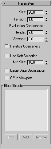
- Size
-
The radius of each metaball for objects other than particles. For particles, the size of each metaball is determined by the size of the particle, which is set by parameters in the particle system. Default=20.
Note: The apparent size of the metaballs is affected by the Tension value. When Tension is set to its lowest possible value, the radius of each metaball accurately reflects the Size setting. Higher Tension values will tighten the surface, and make the metaballs smaller. - Tension
-
Determines how relaxed or tight the surface will be. A smaller value makes a looser surface. This value can range from 0.01 to 1.0. Default=1.0.
- Evaluation Coarseness
-
Sets the coarseness, or density, of the resulting blobmesh. When Relative Coarseness (see following) is off, the Render and Viewport values set the absolute height and width of blobmesh faces, and lower values create a smoother, denser mesh. When Relative Coarseness is on, the height and width of blobmesh faces is determined by the ratio of metaball size to this value. In this case, higher values create a denser mesh. Range (both)=0.001 to 1000.0. Render default=3.0, Viewport default =6.0.
The lower end of the range for both Coarseness settings is 0.001, which allows for high-resolution metaball geometry when Relative Coarseness is off. Using such low values can also cause lengthy calculation delays; if this happens and you wish to halt calculation, press Esc.
- Relative Coarseness
-
Determines how the coarseness values will be used. If this option is turned off, the Render Coarseness and View Coarseness values are absolute, where the height and width of each face on the blobmesh is always equal to the coarseness value. This means the faces on the blobmesh will retain a fixed size even if the metaballs change size. If this option is turned on, the size of each blobmesh face is based on the ratio of the metaball size to the coarseness, which will cause the blobmesh face size to change as the metaballs become larger or smaller. Default=Off.
- Large Data Optimization
-
This option provides an alternate method for calculating and displaying the blobmesh. This method is more efficient than the default method only when a large number of metaballs are present, such as 2,000 or more. Turn on this option only when using a particle system or other object that produces a large number of metaballs. Default=Off.
- Off in Viewport
-
Turns off the display of the blobmesh in viewports. The blobmesh will still appearing in renderings. Default=Off.
- Use Soft Selection
- If soft selection has been used on geometry you add to the blobmesh, turning on this option causes the soft selection to be used for the size and placement of metaballs. Metaballs are placed at selected vertices with the size set by the Size parameter. For vertices that lie within the falloff set on the geometry’s Soft Selection rollout, smaller metaballs are placed. For vertices outside the falloff, no metaballs are placed. This option has an effect only if the Vertex sub-object level for the geometry is still enabled, and Use Soft Selection on the geometry’s Soft Selection rollout is turned on. If Use Soft Selection is turned off either for the blobmesh for the geometry, metaballs are placed at all vertices on the geometry. Default=Off.
- Min Size Sets the minimum size for metaballs within the falloff when Use Soft Selection is turned on. Default=10.0.
Blob Objects group
- [objects list]
- Lists objects in the scene that are part of the blobmesh simulation.
- Pick
-
Allows you to pick objects or particle systems from the screen to add to the blobmesh.
- Add
-
Displays a selection dialog where you can select objects or particle systems to add to the blobmesh.
- Remove
-
Removes objects or particles from the blobmesh.
Particle Flow Parameters rollout

Use this rollout if you have added a Particle Flow system to the blobmesh, and want particles to generate metaballs only during specific events. Before you can specify events on this rollout, you must add the Particle Flow system to the blobmesh on the Parameters rollout.
- All Particle Flow Events
-
When turned on, all Particle Flow Events will generate metaballs. When turned off, only Particle Flow Events specified in the PFlow Events list will generate metaballs.
Particle Flow Events group
- [PFlow events list]
- Lists PFlow events that are part of the blobmesh simulation.
- Add
-
Displays a list of PFlow events in the scene so you can pick events to add to the PFlow Events list.
- Remove
-
Removes the selected event from the PFlow Events list.

Conform Compound Object
Conform is a compound object created by projecting the vertices of one object, called the Wrapper, onto the surface of another object, called the Wrap-To. There is also a space-warp version of this function; see Conform space warp.
- Select an object. > Create panel > (Geometry) > Compound Objects > Object Type rollout > Conform

Conform fits the road to the surface of the hills.
Because the space-warp version is somewhat easier to use, it’s a good idea to read that topic first, try the example, and then return here. This topic provides additional methods of projecting the wrapper vertices.
Note: This tool gives you the ability to morph between any two objects, regardless of the number of vertices in each object. See Vertex Projection Direction group for more information.
Procedures
Example: To create a Conform object:
- Position two objects, one of which will be the Wrapper, and the other the Wrap-To. (For this example, create a box as the Wrap-To object, and then create a larger sphere that completely surrounds it. The sphere will be the Wrapper.)
- Select the Wrapper object (the sphere), and on the Create panel, with (Geometry) active, choose Compound Objects from the drop-down list. On the Object Type rollout, turn on Conform.
Note: Both objects used in Conform must be either mesh objects or objects that can be converted to mesh objects. If the selected Wrapper object is invalid, the Conform button is unavailable.
- Specify the method of vertex projection in the Vertex Projection Direction group. (Use Along Vertex Normals for this example.)
Note: If you were to choose Use Active Viewport, you would next activate whichever viewport looks in the direction that you want to project the vertices. For example, if the Wrapper hovered over a Wrap-To terrain on the home plane, you’d activate the Top viewport.
- Choose Reference, Copy, Move, or Instance to specify the type of cloning to perform on the Wrap-To object. (Choose Instance for this example.)
- Click Pick Wrap-To Object, and then click the object onto which to project the vertices. (You can press the H key and use the Pick Object dialog to select the box.)
The list windows display the two objects, and the compound object is created with the Wrapper object conforming to the Wrap-To object. (In the example, the sphere is wrapped into the shape of the box.)
- Use the various parameters and settings to alter the vertex projection direction, or adjust the vertices that are being projected.
To project a road onto terrain:
- Create the road and terrain objects.
Tip: You can quickly make a terrain by creating a patch grid and applying theNoise modifier to it. For the road, you can use a Loft compound object by lofting a rectangle along a curved line. Both objects must have a sufficient level of detail to conform smoothly.
- Orient both the road and the terrain so you are looking straight down at them in the Top viewport. Position the road so it’s completely above the terrain (higher on the world Z axis).
Note: For the conform projection to work correctly, the road should not extend beyond the boundaries of the terrain when viewed in the Top viewport.
- Select the road object.
- Click Conform.
- In the Pick Wrap-To Object rollout, make sure the Instance option is selected.
- Click Pick Wrap-To Object, and click the terrain.
An instance of the terrain object is created, with the same object color as the road.
- Activate the Top viewport. In the Parameters rollout
 Vertex Projection Direction group, choose Use Active Viewport, and click Recalculate Projection.
 - In the Update group, turn on Hide Wrap-To Object.
This hides the instance of the terrain so you can clearly see the road projected onto it.
The Parameters rollout
Wrapper Parameters group Standoff Distance value sets the number of units by which the road sits above the terrain along the world Z axis. - If necessary, adjust the Standoff Distance to raise or lower the road.
Interface
Pick Wrap-To Object rollout

- Object
-
Displays the name of the selected Wrap-To object.
- Pick Wrap-To Object
-
Click this button, and then select the object to which you want the current object to wrap.
- Reference/Copy/Move/Instance
-
This option lets you specify how the Wrap-To object is transferred to the Conform object. It can be transferred either as a reference, a copy, an instance, or it can be moved, in which case the original is not left behind.
Parameters rollout
Contains all parameters for the Conform object.
Objects group

Provides a list window and two edit fields that let you navigate the compound object and rename its components.
- [list window]
-
Lists the Wrapper and the Wrap-To objects. Click to select an object in the window so that you can access it in the Modifier stack.
- Wrapper Name
-
Lets you rename the wrapper object within the compound Conform object.
- Wrap-To Object Name
-
Lets you rename the Wrap-To object.
Vertex Projection Direction group

Choose one of these seven options to determine the projection of the vertices.
- Use Active Viewport
-
The vertices are projected away (inward) from the active viewport.
- Recalculate Projection
-
Recalculates the projection direction for the active viewport. Because the direction is initially assigned when you pick the Wrap-To object, if you want to change viewports after assignment, click this button to recalculate the direction based on the new active viewport.
- Use Any Object’s Z Axis
-
Lets you use the local Z axis of any object in the scene as a direction. Once an object is assigned, you can alter the direction of vertex projection by rotating the direction object.
- Pick Z-Axis Object
-
Click this button, and then click the object you want to use to indicate the direction of the projection source.
- Object
-
Displays the name of the direction object.
- Along Vertex Normals Projects the vertices of the Wrapper object inward along the reverse direction of its vertex normals. A vertex normal is a vector produced by averaging the normals of all faces attached to that vertex. If the Wrapper object encloses the Wrap-To object, the Wrapper takes on the form of the Wrap-To object.
- Towards Wrapper Center Projects the vertices toward the bounding center of the Wrapper object.
- Towards Wrapper Pivot Projects the vertices toward the original pivot center of the Wrapper object.
- Towards Wrap-To Center Projects the vertices toward the bounding center of the Wrap-To object.
- Towards the Wrap-To Pivot Projects the vertices toward the pivot center of the Wrap-To object.
Note: Towards Wrapper Pivot and Towards the Wrap-To Pivot operate on the position of the original pivot point of the object before the Conform object is created. Once you create the Conform object, it’s a new compound object with a single pivot point.Tip: You can animate the conforming effect by morphing between the compound object and a previously made copy of the original wrapper object. To do this, however, you must turn on Hide Wrap-To Object in the Update group so that the original object and the compound object have the same number of vertices. Using this technique, you can effectively morph between two objects with a different number of vertices.
Wrapper Parameters group

Provides controls that determine how far the vertices are projected.
- Default Projection Distance
-
The distance a vertex in the Wrapper object will move from its original location if it does not intersect the Wrap-To object.
- Standoff Distance
-
The distance maintained between the vertex of the Wrapper object and the surface of the Wrap-To object. For example, if you set Standoff Distance to 5, the vertices can be pushed no closer than 5 units from the surface of the Wrap-To object.
- Use Selected Vertices
-
When turned on, only the selected vertex sub-objects of the Wrapper object are pushed. When turned off, all vertices in the object are pushed, regardless of the Modifier stack selection. To access the Modifier stack of the Wrapper object, select the Wrapper object in the list window, open the Modifier stack, and select the base object name. At this point you can apply a Mesh Select modifier, for example, and select the vertices you want to affect.
Update group

The items in this group determine when the projection for the compound object is recalculated. Because complex compound objects can slow performance, you can use these options to avoid constant calculation.
- Always The object is updated constantly.
- When Rendering The object is recalculated only when the scene is rendered.
- Manually Activates the Update button for manual recalculation.
- Update
-
Recalculates the projection.
- Hide Wrap-To Object
-
When on, hides the Wrap-To object.
Display group
Determines whether the shape operands are displayed.

- Result Displays the result of the operation.
- Operands Displays the operands.


Correctly setting up blueprints so they’re usable in your modeling work-flow can be a frustrating task to say the least, but in today’s Quick Tip you’ll learn how to do just that. Sasa Posloncec will show you the best place to find and download blueprints, how to correctly separate, scale and align them using Photoshop and how to get them up and running inside 3D Studio Max. Get started after the jump!


