Graphic World

Categories
Learning Tutorials Videos

Quick Tip: Assigning Hotkeys & Making Custom Menus In 3d Studio Max

Quick Tip: Assigning Hotkeys & Making Custom Menus In 3d Studio Max

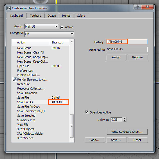
One of the most important steps in building a better, faster workflow is the addition of Hotkeys. These simple shortcut commands might only shave seconds off at a time, but in the long run those seconds can add up to hours. In this quick tip from Chandan Kumar, you’ll learn how to save time and work more efficiently by creating your own custom tool menus right inside of 3ds Max’s UI, and how to setup keyboard shortcuts for the tools you use most.

Note: click the ‘Monitor’ icon to view tutorial in full-screen HD.

Categories
Learning Tutorials Videos

Realistically Integrate a CG Car Into Your Footage

We’ll look at a real world example of a computer generated car model integration into live action footage taken from helicopter. This tutorial covers the full pipeline of camera tracking, 3D scene preparation, rendering, and composing everything into a seamless shot. We’ll wrap up with the removal of the film crew and sky replacement techniques.

Categories
Articles Learning Tutorials

Quick Tip: How to Setup Units & Use the Tape Tool in 3D Studio Max

Quick Tip: How to Setup Units & Use the Tape Tool in 3D Studio Max

In this quick tip, Alex Martin introduces you to two features of 3D Studio Max that many new artists overlook, a correct unit setup and the ever handy tape tool. Working with a correct scene scale is extremely important, especially when it comes to multiple artists working on the same scene, or when recreating accurate lighting for a project. This quick tip will give you a few tips for setting up your units system correctly, and provide a practical example for measuring the distance between objects using the tape tool and how this applies when working with Z-Depth.

Whenever we create a primitive object in 3ds Max, it shows its dimensions without any proper unit by default. For example, I have created a box in the viewport and you can see there is no unit setup defined for its dimensions (Length, Width and Height). However these dimensions have some values, but we don’t know what exactly these are; meter, feet, inches, centimeters or something else?

The majority of 3ds Max users just start working this way, and this is indeed a fatal tendency. If you’re working on an architecture or industrial project, or anything which requires a correct unit setup, then you must take care of it.

Max_Tape_Tool_QT_1

Not working with a correct unit setup can create lots of other problems. Let’s look at it through an example. Say, there are two users A and B, working in 3ds max on two different machines and both are working without setting up the correct unit order. User A has created a biped (scene 1) and user B has made a car (scene 2).

Max_Tape_Tool_QT_2

Now, after merging both projects together (scene 3), it shows the real problem. In scene 3, you can see the ratio mismatch clearly. The biped is too big for the car. This happened, because both users were working without setting up the correct unit order. If they had used the unit setup before, this problem could have been avoided.

Max_Tape_Tool_QT_2a

Now, let’s see how to work with the correct unit setup. Open 3ds Max and first of all go to the Customizemenu. Here click on the Units Setup… option.

Max_Tape_Tool_QT_3

This opens Units Setup window. Here click on the System Unit Setup button to open the System Unit Setup window. By default, it shows 1 unit = 1 inch.

Max_Tape_Tool_QT_3a

This means if you draw a box in the viewport, its dimension values are in inches by default. So in this example, a Length value of  40.0 means 40 inches and so on.

Max_Tape_Tool_QT_3b

Now let’s go back to the Units Setup window. You can choose here a metric unit system also. Just turn on the Metric radio button and select any of the available units (meters, centimeters, kilometers etc). Then click on the OK button.

Max_Tape_Tool_QT_4

Now create a new Box in the viewport, and you’ll see its dimension values are in meters now.

Max_Tape_Tool_QT_4a

You can change the unit system to US standard also. You can see I have changed the system unit to Feet/ Inches and now the same box’s dimension values are displaying in feet/ inches. So this is the way to get a correct measurement in 3ds Max.

Max_Tape_Tool_QT_4b

Now let’s see how we can use unit setup in a different case. I have created a biped in the viewport. The question is, how to determine the exact height of the biped? Since the biped doesn’t have any dimension values, we need to apply a trick to know the height of the biped.

Max_Tape_Tool_QT_5

There is a simple trick to set the proper height of the biped. Create a Box of the same height beside the biped. Now check the height value of the box. It shows 16 feet and 5 inches. This means the biped has the same height as well. So this is the trick to determine and setup the proper height of a biped.

Max_Tape_Tool_QT_5a

Now let’s see how to determine the proper distance between two objects in 3ds Max. I have created two objects in the viewport, and now we have to get the exact distance between the two.

Max_Tape_Tool_QT_6

To know the distance between objects, we’ll use Tape tool. Click on the Helper icon and then select theTape tool.

Max_Tape_Tool_QT_6a

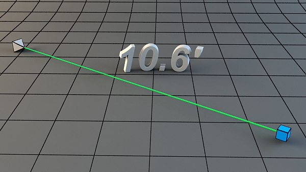
With the Tape tool selected, first click on the starting point, don’t release the mouse button and then click on the end point. The starting point of the tape tool is called the head/ tape and the end point is called the tail/ target. The connecting line in green between the head and tail represents the current distance.

Max_Tape_Tool_QT_7

If you select the head of the Tape tool, you can see the exact length or distance between the head and tail points.

Max_Tape_Tool_QT_8

If you turn on the Specify Length option, you’ll see the Length value gets changed and the green line of the tape tool exceeds a bit.

Max_Tape_Tool_QT_9

You can easily set it correctly by the spinner for the Length parameter.

Max_Tape_Tool_QT_10

Let’s see through an example, how the tape tool helps in Z-Depth channel extraction. Press the F10 key on the keyboard to open the Render Setup window. Here go to the Render Elements tab and click on Add. This opens the Render Elements sub-window. Here select Z Depth and then click on OK.

Max_Tape_Tool_QT_11

Inside the Z Depth Element Parameters, there are two options, Z Min and Z Max. If you want the correct Z Depth value, then you must know the correct Z Min and Z Max values, which are actually the distances from the camera focus to the target objects.

Max_Tape_Tool_QT_12

So you can see how important the measuring tools are in 3ds Max. I hope you have enjoyed this quick tip tutorial.

Categories
Articles Learning Tutorials

Creating a Dynamic Wrecking Ball Simulation Using Mass FX and Constraints in 3ds Max

1. Creating the Chain

Open 3ds Max. Go to Shapes > Splines > Ellipse and draw an oval shape in the front viewport.

Draw an oval shape
Draw an oval shape

With the oval shape selected, open the Rendering rollout tab. Turn on Enable In Renderer and Enable In Viewport options. Increase the Thickness value to 7.

Rendering rollout
Rendering rollout

Right click on the oval shape and turn it into Editable Poly.

Editable Poly
Editable Poly

With the oval poly shape selected, click on Hierarchy panel. Enable Affect Pivot Only option and drag the pivot of the oval poly shape to the extreme right.

Don’t forget to turn off the Affect Pivot Only option after that.

Hierarchy
Hierarchy 

Make a copy of the oval poly shape and rotate it. Both objects must not intersect each other.

Make a copy of the oval poly shape

Make several copies of the oval shapes to form a chain link.

Make several copies
Make several copies

With the chain selected, go to Mass FX toolbar and select Set Selected as Dynamic Rigid Body option.

Set Selected as Dynamic Rigid Body
Set Selected as Dynamic Rigid Body 

With the first oval poly shape from the left side selected, go to Constrains > Create Universal Constraint.

Constrains Create Universal Constraint
Constrains > Create Universal Constraint

It creates a UConstraint at the pivot point of the oval poly shape.

UConstraint
UConstraint

For the first oval poly object, its parent would be the next oval poly object.

Click on Parent tab and select the next oval poly object as the parent of the first oval poly object. Turn onFree radio buttons of Swing Y, Swing Z and Twist properties.

Swing Y Swing Z and Twist properties
Swing Y, Swing Z and Twist properties

You can lower the UConstraint icon size also. Put a smaller value in Icon Size.

UConstraint
UConstraint

Following the same way, with the next oval poly object selected, go to Constraints > Create Universal Constraint.

Constraints Create Universal Constraint
Constraints > Create Universal Constraint

It creates a UConstraint at the pivot point of the oval poly shape.

UConstraint
UConstraint 

For this oval poly object, its parent would be the next oval poly object. So, click on Parent tab and select the next oval poly object as the parent of the selected oval poly object. Turn on Free radio buttons of Swing Y, Swing Z and Twist properties.

Swing Y Swing Z and Twist properties
Swing Y, Swing Z and Twist properties

Following the same way, keep making constraints for each oval poly object one by one. After a couple of minutes, you will have the completed chain.

The completed chain
The completed chain

Create a sphere. Put it at the end of the chain link. This will act as the wrecking ball.

Create a sphere
Create a sphere

Put the pivot of the sphere at the edge of the sphere as shown in the following image.

Put the pivot of the sphere at the edge
Put the pivot of the sphere at the edge 

Make this sphere as a dynamic rigid body.

Make this sphere as a dynamic rigid body

Apply Universal Constraint to the sphere.

Universal Constraint

For this sphere object, its parent would be the first oval poly object. Click on Parent tab and select the first oval poly object as the parent of the selected sphere object. Turn on Free radio buttons of Swing Y, Swing Z and Twist properties.

Swing Y Swing Z and Twist properties
Swing Y, Swing Z and Twist properties

Create a small low poly sphere at the extreme right end of the chain.

Create a small low poly sphere

This time, make this sphere as a Kinematic Rigid Body.

Kinematic Rigid Body

With the indicated oval poly object selected, apply Universal Constraint to it.

Universal Constraint
Universal Constraint 

Select the low poly sphere as the parent of it. Turn on Free radio buttons of Swing Y and Swing Z. Keep the radio button of Twist turned off.

Turn off Twist button

With the wrecking ball sphere selected, click on Mass FX Tool icon. Inside the Mass FX Tool window, go toMulti-Object Editor tab and put the Mass value as 5.

Multi-Object Editor
Multi-Object Editor

Click on Start Simulation icon. You will see a fine simulation of chained wrecking ball in the viewport.

Start Simulation
Start Simulation

Go to scriptspot.com and download Fracture Voronoi script.

Fracture Voronoi
Fracture Voronoi 

Save the script in the 3ds Max Scripts folder.

Scripts folder
Scripts folder

Create a box in the viewport to make a wall.

Create a box
Create a box 

With the wall selected, go to Max Script > Run Script.

Max Script Run Script
Max Script > Run Script

It opens the Choose Editor file window. Select the Fracture Voronoi script and click on Open.

Fracture Voronoi run

It opens the Fracture Voronoi script window. Click on Pick Object button and then select the wall in the viewport.

Fracture Voronoi script window

I have set the Nb parts as 40 since I want the wall to be broken into forty different chunks. I’ve selected theUniform color option as I want all the chunks in a same color.  

Nb parts as 40
Nb parts as 40

Click on Break in 40 button. It breaks the box wall into 40 pieces.

Break in 40
Break in 40

You can further break each broken piece into several more chunks. Select a broken piece and then repeat the process from Steps 2 to 6.

repeat the process from Step 2 to 6

With all wall chunks selected, make them as Dynamic Rigid Body.

Dynamic Rigid Body
Dynamic Rigid Body

With all wall chunks selected, go to Multi-Object Editor tab and put the Mass value as 5. Turn on Start in Sleep Mode option.

Multi-Object Editor
Multi-Object Editor

Click on Start Simulation button. You will see the wall shattering simulation in the viewport.

Start Simulation
Start Simulation

Once you are satisfied with the simulation result, click on Bake All tab to bake all simulation.

Bake All
Bake All

Mass FX is a great dynamics tool in 3ds Max. It has replaced Reactor and has more controls over the dynamic simulation than ever.

Categories
Articles Learning Tutorials

Create A 3D Floor Plan Model From An Architectural Schematic In Blender

Create A 3D Floor Plan Model From An Architectural Schematic In Blender

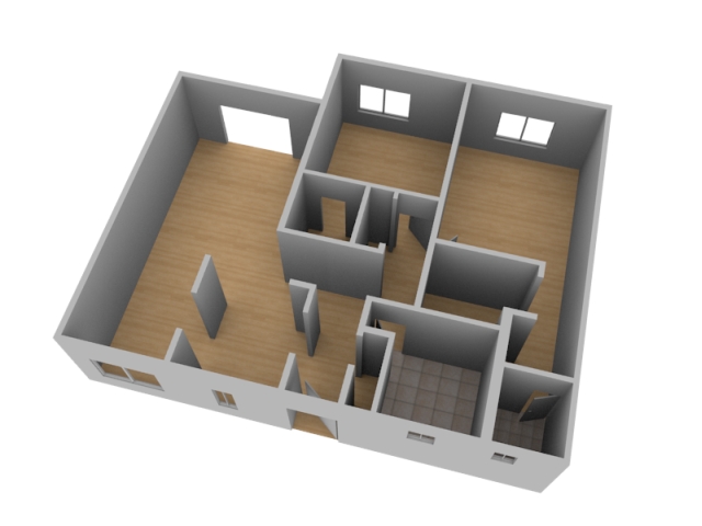
In this tutorial you’ll learn how to create a 3D floor plan model from an 2D architectural drawing. Karan Shah will show you some simple, yet effective techniques for constructing the walls, windows and doors following a basic interior schematic in Blender. With the model complete we’ll add materials and textures, and do a final render of the scene.

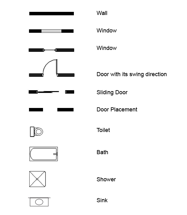
Floor Plans are simply a drawing or a diagram showing a top view of a site layout. You can see the picture to understand the meaning of some basic symbols used. More can be found
here (pdf).

Free Blender Tutorial Create A 3D Floor Plan From An Architectural Schematic

In a new file, select all objects with the ‘A’ key and press ‘Del’ to delete them. Press ‘N’ to bring up our View properties. In the Background Image Panel, add your reference image. Here I have used image courtesy ofLiamKeiranCooper Ltd who kept the picture in public domain.

Free Blender Tutorial Create A 3D Floor Plan From An Architectural Schematic

Press ‘7’ on the NumPad to get into the Top view. Here you can see the background image. The view must be set to ‘orthographic’ in order to see the image. You can toggle between the ortho and perspective views with the ‘5’ key on the Numpad. Press Shift+A and add a Plane.

Free Blender Tutorial Create A 3D Floor Plan From An Architectural Schematic

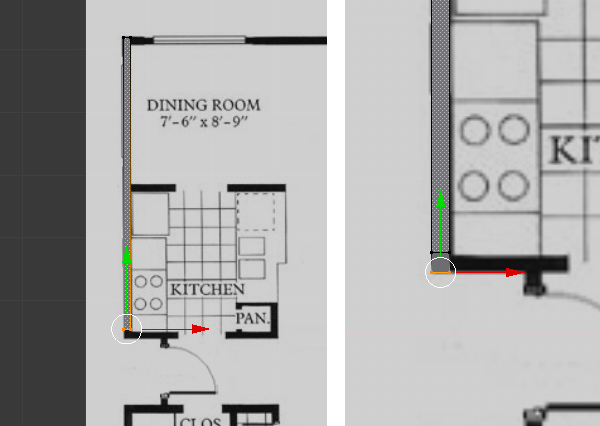
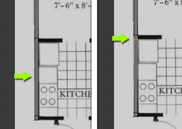
With the Plane selected, press ‘TAB’ to get into ‘Edit’ mode. Select all the vertices with the ‘A’ key, or press ‘B’ to drag select them. Press ‘G’ and move them to the top left corner. You toggle the viewport shading between solid and wireframe with ‘Z’ key. Press ‘S’ and move the mouse to scale them down to fit the width of the wall (as shown below.)

Free Blender Tutorial Create A 3D Floor Plan From An Architectural Schematic

Now we will cover all the black solid areas i.e. the walls. This will include the windows as they are part of the walls and will be added later. Any type of door whether it’s a slider or normal, is to be left out. Select the bottom two vertices (press ‘B’ to drag select or Hold ‘Shift’ and Right click for multiple select.) And move them down just before the wall turns left. Press ‘E’ and extrude the wall again until you reach the edge.

Free Blender Tutorial Create A 3D Floor Plan From An Architectural Schematic

Select the right two vertices and press ‘E’ to extrude, and match the reference.

Free Blender Tutorial Create A 3D Floor Plan From An Architectural Schematic

Now, in order to extrude out a face from the middle, we need to add an Edge Loop. Hover your mouse over the face, and press ‘CTRL+R’ and Left Click to confirm. Move the mouse up and down and then Left click again to confirm its position.

Free Blender Tutorial Create A 3D Floor Plan From An Architectural Schematic

Create another edge loop just below the previous one using the same method, matching the width of the wall to be extruded.

Free Blender Tutorial Create A 3D Floor Plan From An Architectural Schematic

Select the two vertices and extrude the wall.

Free Blender Tutorial Create A 3D Floor Plan From An Architectural Schematic

Create another edge loop on the corner and extrude the right edge.

Free Blender Tutorial Create A 3D Floor Plan From An Architectural Schematic

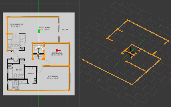
Using the techniques above (extrude and edge loop division) fill all the solid black lines of the reference image with the mesh.

Free Blender Tutorial Create A 3D Floor Plan From An Architectural Schematic

To start a new separate wall, duplicate the last edge and then start extruding it. Select the last edge and press ‘Shift+D’ to Duplicate it, and left click to confirm. Move it with the Move control widget or press ‘G’ key of the keyboard. And continue extruding the mesh along to match the reference.

Free Blender Tutorial Create A 3D Floor Plan From An Architectural Schematic

Complete the walls with the techniques you learned from above steps.

Free Blender Tutorial Create A 3D Floor Plan From An Architectural Schematic

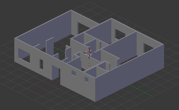
After completing the wall, select all the vertices and then press ‘E’ to extrude them along the Z axis. Now we see that the structure is taking shape. The height should be equivalent to a door.

Free Blender Tutorial Create A 3D Floor Plan From An Architectural Schematic

Press ‘Ctrl+TAB’ and select ‘Edge’ in the mesh select mode menu. Select the top two corner edges of a door (hold shift + right click to multiple select) and press ‘F’ to make a Face between them. Do this for all doors. Refer to your image and always check from all views.

Free Blender Tutorial Create A 3D Floor Plan From An Architectural Schematic

Press ‘3’ on the Numpad to get into side view, and Press ‘Z’ to get into wireframe view so that we can see all the vertices behind are visible and can be selected. Press ‘B’ to drag select all the top vertices or edges, then Press ‘E’ to extrude them. This will reach the final height of the wall.

Free Blender Tutorial Create A 3D Floor Plan From An Architectural Schematic

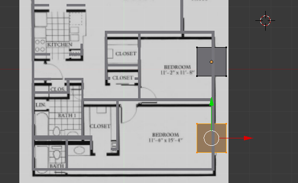
Now we will place the windows. Press ‘TAB’ to get out of the Edit mode, and in object mode, press ‘Shift+A’ and add a ‘Cube’. In the Top view, size (press ‘S’ to scale) and place it where the window is on the reference image.

Free Blender Tutorial Create A 3D Floor Plan From An Architectural Schematic

In the side view, the top part of window should align to the top of door. Press ‘TAB’ to enter into the edit mode to adjust the vertices. Adjust the bottom height of the window too. The width of the cube should be such that it should be half inside and half outside. See image below.

Free Blender Tutorial Create A 3D Floor Plan From An Architectural Schematic

Select the Wall mesh with Right click, and in the Properties button window, click on ‘Object Modifiers’.

Free Blender Tutorial Create A 3D Floor Plan From An Architectural Schematic

Click on ‘Add Modifiers’ and select ‘Boolean’.

Free Blender Tutorial Create A 3D Floor Plan From An Architectural Schematic

In the Boolean modifiers panel, select ‘Cube’ in the Object, and ‘Difference’ under ‘Operation’.

Free Blender Tutorial Create A 3D Floor Plan From An Architectural Schematic

To see the effect – Select the cube and press ‘H’ to hide it. You will see that there is a “hole” in the wall the size and shape of the cube. Press ‘Alt+H’ to ‘Unhide’ the Cube.

Free Blender Tutorial Create A 3D Floor Plan From An Architectural Schematic

Now select the Cube (window) and in the ‘Edit’ mode, select all the vertices and press ‘Shift+D’ to make a duplicate. Place this new cube in the location of the next window.

Free Blender Tutorial Create A 3D Floor Plan From An Architectural Schematic

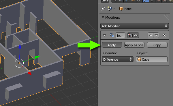
Now press ‘Tab’ to get out of ‘Edit’ mode, and select the Wall mesh and press ‘Apply’ in the ‘Boolean’ Modifier panel. The holes are now part of the geometry.

Free Blender Tutorial Create A 3D Floor Plan From An Architectural Schematic

Move the Cube to see the windows.

Free Blender Tutorial Create A 3D Floor Plan From An Architectural Schematic

Similarly create all the needed windows with this Boolean modifier. Try doing them one by one, adjust the size and position of the cube according to the specific window.

Free Blender Tutorial Create A 3D Floor Plan From An Architectural Schematic

Now we will create the Floor. In ‘Object’ mode and in the Top view, press ‘Shift+A’ and add a ‘Plane’. Press ‘Tab’ to get into ‘Edit’ mode and adjust the vertices accordingly so that it covers the walls. Create Edge Loops or Extrude the edges where necessary.

Free Blender Tutorial Create A 3D Floor Plan From An Architectural Schematic

Make sure that there are no gaps between the edges of the floor and walls. Also in the Side view, move the floor down so it’s aligned with the bottom of the walls.

Free Blender Tutorial Create A 3D Floor Plan From An Architectural Schematic

To make doors, add a new’Cube’. And in ‘Edit’ mode, press / on the Numpad for Local view (this will show only the selected object.)  In the Top view, Move or Scale the vertices to give it a nice shape. Refer to the image for the height and width.

Free Blender Tutorial Create A 3D Floor Plan From An Architectural Schematic

In the Top view, and in ‘Edit’ mode. Move all the vertices of the door along the Y axis, so that the center point of the object (orange dot) should be at the corner (see image.) This will set the transform orientation of the object from that corner. Press ‘TAB’ to get out of edit mode and then press’R’ to Rotate and see the difference.

Free Blender Tutorial Create A 3D Floor Plan From An Architectural Schematic

While in the edit mode, add a new ‘Cylinder’. Rotate and scale it down to create the doorknob (you can add more details if you like.) Press ‘TAB’ to get out of edit mode.

Free Blender Tutorial Create A 3D Floor Plan From An Architectural Schematic

With the help of the reference image, place the doors in the correct positions (press ‘Shift+D’ to make duplicates.)

Free Blender Tutorial Create A 3D Floor Plan From An Architectural Schematic

Now we will create the window frame. Start with another new ‘Cube’, and press ‘TAB’ to enter into ‘Edit’ mode. Press the ‘Z’ key to toggle wireframe view, so that we can select the back vertices too. Press ‘3’ on the Numpad to get into side view and then extrude the faces as shown in the image to make the window frame. Press ‘TAB’ to exit out of edit mode, and press / on the numpad again to get back to the scene.

Free Blender Tutorial Create A 3D Floor Plan From An Architectural Schematic

Scale and place the window frames on the walls. Make duplicates and place them according to the image.

Free Blender Tutorial Create A 3D Floor Plan From An Architectural Schematic

Now we will add a texture to the floor. Right Click on the Floor object to select it. And in the Properties window, click on the ‘Materials’ Icon. Add a New material and name it ‘Floor’, increase the ‘Diffuse’ intensity and reduce the ‘Specular’ intensity.

Free Blender Tutorial Create A 3D Floor Plan From An Architectural Schematic

Next we will add an image to the floor. (I got mine from Here.) Click on the ‘Texture’ icon next to the Material icon, and then Click on the ‘New’ button. Select ‘Image or Movie’ for the Type and in the Image panel, click on “Open’ and browse for the image.

Free Blender Tutorial Create A 3D Floor Plan From An Architectural Schematic

You can preview the texture in the 3d View. Press ‘N’ to bring up the ‘View Properties’ and in the ‘Display’ panel, select GLSL in the ‘Shading” menu (you’ll need to add some lights in the 3d view to see the texture.) Now press ‘N’ again to hide the view properties panel.

Free Blender Tutorial Create A 3D Floor Plan From An Architectural Schematic

Back to the Image Texture properties, scroll down to the Mapping Panel and increase the Size of X and Y to5 or 6 depending upon your image file.

Free Blender Tutorial Create A 3D Floor Plan From An Architectural Schematic

Now to add a separate floor to the Bathrooms, we will add a new ‘Plane’ and adjust it’s dimensions and place it just above the wooden floor so that it’s hidden.

Free Blender Tutorial Create A 3D Floor Plan From An Architectural Schematic

Apply an image, just like we did on the floor (I got mine from Here.) Duplicate the Plane and adjust it’s geometry by scaling and extruding for the second bathroom.

Free Blender Tutorial Create A 3D Floor Plan From An Architectural Schematic

Select the walls and add a New material to them. Choose any color and Increase the ‘Diffuse’ intensity and set the ‘Specular’ to 0.0

Free Blender Tutorial Create A 3D Floor Plan From An Architectural Schematic

Similarly assign the materials to the windows and doors. You can assign the same material to any object by selecting the material from the list.

Free Blender Tutorial Create A 3D Floor Plan From An Architectural Schematic

Now we will prepare the scene for rendering. Make sure you are Not in ‘Edit’ mode (press ‘TAB’ to toggle Edit mode on/off.) Press ‘7’ on the Numpad to get into the Top view, then press ‘Shift+A’ to add a camera.

Free Blender Tutorial Create A 3D Floor Plan From An Architectural Schematic

Rotate and place it however you like. Press ‘0’ on the Numpad to get into camera view.

Free Blender Tutorial Create A 3D Floor Plan From An Architectural Schematic

Click on the ‘World’ settings and change the ‘Horizon Colour’ to white, then turn on ‘Ambient Occlusion’ and in the ‘Gather’ panel, increase the samples to 16. In the 3D view delete any lights if they exists.

Free Blender Tutorial Create A 3D Floor Plan From An Architectural Schematic

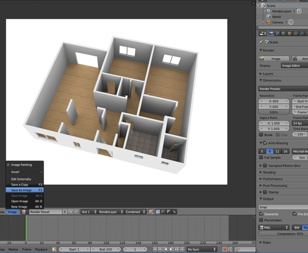
Click on the ‘Render Settings’ button in the property window, and change the Dimensions (resolution) to your desired size. Down in the ‘Output’ panel, choose the file format for your render.

Step 1 Image

Press ‘F12’ or click on the ‘Image’ button in the render panel. Press ‘F3’ or click on ‘Image > Save image as‘ to save the image.

Your 3D Floor map is now ready!

Free Blender Tutorial Create A 3D Floor Plan From An Architectural Schematic