Graphic World

Categories
Learning Tutorials

BlobMesh Compound Object – 3D Max Tutorial

BlobMesh Compound Object

compound object creates a set of spheres from geometry or particles, and connects the spheres together as if they were made of a soft, liquid substance. When the spheres move within a certain distance of one another, they connect together. When they move apart, they take on a spherical form again.
  • Create panel > (Geometry) > Compound Objects > Object Type rollout >BlobMesh
  • Standard menu: Create menu > Compound > BlobMesh
  • Enhanced menu: Objects menu > Compound Objects > BlobMesh

In the 3D industry, the general term for spheres that operate in this way is metaballs. The BlobMesh compound object generates metaballs based on specified objects in the scene, and the metaballs, in turn, form a mesh result called a blobmesh. A blobmesh is ideal for simulating thick liquids and soft substances that move and flow when animated.

When you associate an object or particle system with the BlobMesh compound object, the metaballs are placed and sized differently depending on the object used to generate them:

  • For geometry and shapes, a metaball is placed at each vertex, and the size of each metaball is determined by the size of the original BlobMesh object. Soft selection can be used to vary the sizes of the metaballs.
  • For particles, a metaball is placed at each particle, and the size of each metaball is determined by the size of the particle on which it’s based.
  • For helpers, a metaball is placed at the pivot point, and the size of the metaball is determined by the original BlobMesh object.
Note: You can apply motion blur to a BlobMesh object to enhance the effects of motion in renderings. For particle systems other than Particle Flow, use Image motion blur. For Particle Flow particle systems and all other types of objects including geometry, shapes, and helpers, use Object motion blur.

Procedures

To create a blobmesh from geometry or helpers:

  1. Create one or more geometry or helper objects. If the scene requires animation, animate the objects as desired.
  2. Click BlobMesh, and click anywhere on the screen to create the initial metaball.
  3. Go to the Modify panel.
  4. In the Blob Objects group, click Add. Select the objects you wish to use to create metaballs. A metaball appears at each vertex of each selected object, or at the centers of helper objects.
  5. In the Parameters rollout, set the Size parameter as necessary to cause the metaballs to connect.

To create a blobmesh with soft selection on geometry:

  1. Create a geometry object, and convert it to an Editable Mesh or Editable Poly.
  2. Apply a Mesh Select modifier to the object, and select some of the vertices on the object.
  3. In the Soft Selection rollout, turn on Use Soft Selection. Set the Falloff value as desired.
  4. Apply a Turn to Mesh or Turn to Poly modifier to the object.

    This will retain the soft selection and pass it up the stack regardless of whether you exit the sub-object mode.

  5. On the Create panel, with (Geometry) active, choose Compound Objects from the drop-down list. On the Object Type rollout, turn on BlobMesh. Click anywhere in a viewport to create the initial metaball.
  6. Go to the Modify panel.
  7. In the Blob Objects group, click Add. Select the Editable Mesh or Editable Poly object.

    A metaball appears at each vertex of the selected object.

  8. In the Parameters rollout, turn on Use Soft Selection.

    Metaballs are limited to those vertices that are affected by the soft selection.

  9. Set the Size and Min. Size parameters to set the sizes of the metaballs.

To create a blobmesh with soft selection on a spline:

  1. Create the spline, and convert it to an Editable Spline.
  2. In the Rendering rollout, turn on both Enable In Renderer and Enable In Viewport.
  3. Apply a Mesh Select modifier, and select the appropriate vertices for soft selection.
  4. In the Soft Selection rollout, turn on Use Soft Selection. Set the Falloff value as desired.
  5. Apply a Turn to Mesh or Turn to Poly modifier to the object.

    This will retain the soft selection and pass it up the stack regardless of whether you exit the sub-object mode.

  6. On the Create panel, with (Geometry) active, choose Compound Objects from the drop-down list. On the Object Type rollout, turn on BlobMesh. Click anywhere in a viewport to create the initial metaball.
  7. Go to the Modify panel.
  8. In the Blob Objects group, click Add. Select the Editable Spline.

    A metaball appears at each vertex of the selected object.

  9. In the Parameters rollout, turn on Use Soft Selection.

    Metaballs are limited to those vertices that are affected by the soft selection.

  10. Set the Size and Min. Size parameters to set the sizes of the metaballs.

To create a blobmesh from a particle system:

When you use BlobMesh with a particle system, a metaball is created at each particle’s location. The size of the metaball is determined by the size of the particle.

  1. Create a particle system, and set up its parameters to animate the particles.
  2. On the Create panel, with (Geometry) active, choose Compound Objects from the drop-down list. On the Object Type rollout, turn on BlobMesh. Click anywhere in a viewport to create the initial metaball.
  3. Go to the Modify panel.
  4. In the Blob Objects group, click Add. Select the particle system. A metaball appears at each particle in the system.
  5. If you have added a Particle Flow system to the blobmesh and you want to create metaballs only for particles in specific events, click Add on the Particle Flow Parameters rollout to choose the events from a list.
    Tip: If you need to prevent the particles from rendering, do not hide them as this can prevent the blobmesh from generating correctly. Instead, turn off the particle system’s Renderable option on the Object Properties dialog.

Interface

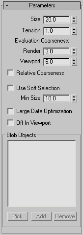
Parameters rollout
Size

The radius of each metaball for objects other than particles. For particles, the size of each metaball is determined by the size of the particle, which is set by parameters in the particle system. Default=20.

Note: The apparent size of the metaballs is affected by the Tension value. When Tension is set to its lowest possible value, the radius of each metaball accurately reflects the Size setting. Higher Tension values will tighten the surface, and make the metaballs smaller.
Tension

Determines how relaxed or tight the surface will be. A smaller value makes a looser surface. This value can range from 0.01 to 1.0. Default=1.0.

Evaluation Coarseness

Sets the coarseness, or density, of the resulting blobmesh. When Relative Coarseness (see following) is off, the Render and Viewport values set the absolute height and width of blobmesh faces, and lower values create a smoother, denser mesh. When Relative Coarseness is on, the height and width of blobmesh faces is determined by the ratio of metaball size to this value. In this case, higher values create a denser mesh. Range (both)=0.001 to 1000.0. Render default=3.0, Viewport default =6.0.

The lower end of the range for both Coarseness settings is 0.001, which allows for high-resolution metaball geometry when Relative Coarseness is off. Using such low values can also cause lengthy calculation delays; if this happens and you wish to halt calculation, press Esc.

Relative Coarseness

Determines how the coarseness values will be used. If this option is turned off, the Render Coarseness and View Coarseness values are absolute, where the height and width of each face on the blobmesh is always equal to the coarseness value. This means the faces on the blobmesh will retain a fixed size even if the metaballs change size. If this option is turned on, the size of each blobmesh face is based on the ratio of the metaball size to the coarseness, which will cause the blobmesh face size to change as the metaballs become larger or smaller. Default=Off.

Large Data Optimization

This option provides an alternate method for calculating and displaying the blobmesh. This method is more efficient than the default method only when a large number of metaballs are present, such as 2,000 or more. Turn on this option only when using a particle system or other object that produces a large number of metaballs. Default=Off.

Off in Viewport

Turns off the display of the blobmesh in viewports. The blobmesh will still appearing in renderings. Default=Off.

Use Soft Selection
If soft selection has been used on geometry you add to the blobmesh, turning on this option causes the soft selection to be used for the size and placement of metaballs. Metaballs are placed at selected vertices with the size set by the Size parameter. For vertices that lie within the falloff set on the geometry’s Soft Selection rollout, smaller metaballs are placed. For vertices outside the falloff, no metaballs are placed. This option has an effect only if the Vertex sub-object level for the geometry is still enabled, and Use Soft Selection on the geometry’s Soft Selection rollout is turned on. If Use Soft Selection is turned off either for the blobmesh for the geometry, metaballs are placed at all vertices on the geometry. Default=Off.

  • Min Size Sets the minimum size for metaballs within the falloff when Use Soft Selection is turned on. Default=10.0.
Blob Objects group
[objects list]
Lists objects in the scene that are part of the blobmesh simulation.
Pick

Allows you to pick objects or particle systems from the screen to add to the blobmesh.

Add

Displays a selection dialog where you can select objects or particle systems to add to the blobmesh.

Remove

Removes objects or particles from the blobmesh.

Particle Flow Parameters rollout

Use this rollout if you have added a Particle Flow system to the blobmesh, and want particles to generate metaballs only during specific events. Before you can specify events on this rollout, you must add the Particle Flow system to the blobmesh on the Parameters rollout.

All Particle Flow Events

When turned on, all Particle Flow Events will generate metaballs. When turned off, only Particle Flow Events specified in the PFlow Events list will generate metaballs.

Particle Flow Events group
[PFlow events list]
Lists PFlow events that are part of the blobmesh simulation.
Add

Displays a list of PFlow events in the scene so you can pick events to add to the PFlow Events list.

Remove

Removes the selected event from the PFlow Events list.

Categories
Articles Learning Tutorials

Creating a Dynamic Wrecking Ball Simulation Using Mass FX and Constraints in 3ds Max

1. Creating the Chain

Open 3ds Max. Go to Shapes > Splines > Ellipse and draw an oval shape in the front viewport.

Draw an oval shape
Draw an oval shape

With the oval shape selected, open the Rendering rollout tab. Turn on Enable In Renderer and Enable In Viewport options. Increase the Thickness value to 7.

Rendering rollout
Rendering rollout

Right click on the oval shape and turn it into Editable Poly.

Editable Poly
Editable Poly

With the oval poly shape selected, click on Hierarchy panel. Enable Affect Pivot Only option and drag the pivot of the oval poly shape to the extreme right.

Don’t forget to turn off the Affect Pivot Only option after that.

Hierarchy
Hierarchy 

Make a copy of the oval poly shape and rotate it. Both objects must not intersect each other.

Make a copy of the oval poly shape

Make several copies of the oval shapes to form a chain link.

Make several copies
Make several copies

With the chain selected, go to Mass FX toolbar and select Set Selected as Dynamic Rigid Body option.

Set Selected as Dynamic Rigid Body
Set Selected as Dynamic Rigid Body 

With the first oval poly shape from the left side selected, go to Constrains > Create Universal Constraint.

Constrains Create Universal Constraint
Constrains > Create Universal Constraint

It creates a UConstraint at the pivot point of the oval poly shape.

UConstraint
UConstraint

For the first oval poly object, its parent would be the next oval poly object.

Click on Parent tab and select the next oval poly object as the parent of the first oval poly object. Turn onFree radio buttons of Swing Y, Swing Z and Twist properties.

Swing Y Swing Z and Twist properties
Swing Y, Swing Z and Twist properties

You can lower the UConstraint icon size also. Put a smaller value in Icon Size.

UConstraint
UConstraint

Following the same way, with the next oval poly object selected, go to Constraints > Create Universal Constraint.

Constraints Create Universal Constraint
Constraints > Create Universal Constraint

It creates a UConstraint at the pivot point of the oval poly shape.

UConstraint
UConstraint 

For this oval poly object, its parent would be the next oval poly object. So, click on Parent tab and select the next oval poly object as the parent of the selected oval poly object. Turn on Free radio buttons of Swing Y, Swing Z and Twist properties.

Swing Y Swing Z and Twist properties
Swing Y, Swing Z and Twist properties

Following the same way, keep making constraints for each oval poly object one by one. After a couple of minutes, you will have the completed chain.

The completed chain
The completed chain

Create a sphere. Put it at the end of the chain link. This will act as the wrecking ball.

Create a sphere
Create a sphere

Put the pivot of the sphere at the edge of the sphere as shown in the following image.

Put the pivot of the sphere at the edge
Put the pivot of the sphere at the edge 

Make this sphere as a dynamic rigid body.

Make this sphere as a dynamic rigid body

Apply Universal Constraint to the sphere.

Universal Constraint

For this sphere object, its parent would be the first oval poly object. Click on Parent tab and select the first oval poly object as the parent of the selected sphere object. Turn on Free radio buttons of Swing Y, Swing Z and Twist properties.

Swing Y Swing Z and Twist properties
Swing Y, Swing Z and Twist properties

Create a small low poly sphere at the extreme right end of the chain.

Create a small low poly sphere

This time, make this sphere as a Kinematic Rigid Body.

Kinematic Rigid Body

With the indicated oval poly object selected, apply Universal Constraint to it.

Universal Constraint
Universal Constraint 

Select the low poly sphere as the parent of it. Turn on Free radio buttons of Swing Y and Swing Z. Keep the radio button of Twist turned off.

Turn off Twist button

With the wrecking ball sphere selected, click on Mass FX Tool icon. Inside the Mass FX Tool window, go toMulti-Object Editor tab and put the Mass value as 5.

Multi-Object Editor
Multi-Object Editor

Click on Start Simulation icon. You will see a fine simulation of chained wrecking ball in the viewport.

Start Simulation
Start Simulation

Go to scriptspot.com and download Fracture Voronoi script.

Fracture Voronoi
Fracture Voronoi 

Save the script in the 3ds Max Scripts folder.

Scripts folder
Scripts folder

Create a box in the viewport to make a wall.

Create a box
Create a box 

With the wall selected, go to Max Script > Run Script.

Max Script Run Script
Max Script > Run Script

It opens the Choose Editor file window. Select the Fracture Voronoi script and click on Open.

Fracture Voronoi run

It opens the Fracture Voronoi script window. Click on Pick Object button and then select the wall in the viewport.

Fracture Voronoi script window

I have set the Nb parts as 40 since I want the wall to be broken into forty different chunks. I’ve selected theUniform color option as I want all the chunks in a same color.  

Nb parts as 40
Nb parts as 40

Click on Break in 40 button. It breaks the box wall into 40 pieces.

Break in 40
Break in 40

You can further break each broken piece into several more chunks. Select a broken piece and then repeat the process from Steps 2 to 6.

repeat the process from Step 2 to 6

With all wall chunks selected, make them as Dynamic Rigid Body.

Dynamic Rigid Body
Dynamic Rigid Body

With all wall chunks selected, go to Multi-Object Editor tab and put the Mass value as 5. Turn on Start in Sleep Mode option.

Multi-Object Editor
Multi-Object Editor

Click on Start Simulation button. You will see the wall shattering simulation in the viewport.

Start Simulation
Start Simulation

Once you are satisfied with the simulation result, click on Bake All tab to bake all simulation.

Bake All
Bake All

Mass FX is a great dynamics tool in 3ds Max. It has replaced Reactor and has more controls over the dynamic simulation than ever.

Categories
Post

Basic Modelling Techniques in 3ds Max

Basic Modelling Techniques in 3ds Max
526_tid_41.jpg
Here I will show you some of the basic concepts that many students of Max might overlook because they are focused on modelling characters right off the bat. While this is fine, it also makes for a frustrating experience when someone new to Max wishes to unleash their creativity.Therefore this is my main focus here, to help you understand some of the basic things you should have under your belt concerning using this programme in order to free the artist within you!What we are going to start with is learning how to use our Primitives to enable us to quickly get modelling. This is a powerful way to not only create or model quickly, but it can also be a great way of getting some ideas down in 3D space. Remember the point here is to unleash your creativity!The first thing that we must have in our minds is what we are going to model. However, sometimes just letting yourself go is a great way to explore your own creativity. But for this project I am going to begin thinking that we are going to try and model some kind of reactor. This is where I will start, but if we end up somewhere else, it’ll be okay because if our creativity begins leading us down a different path it is best to follow it. Of course, if you are being paid to model something specific then veering off that path will not end well for you. But with this exercise – which is exactly what this is going to be: an exercise – we will not have those constraints.Let’s begin!

1. Open Max, and under the Create tab change the Standard Primitives drop down to Extended Primitives, and then create a Chamfer Cylinder in the centre of the Perspective view. Remember that most of the Extended Primitives have 3 creation parameters that must be created: Radius, Height and Fillet. Here is what it should look with all three parameters created (Fig.01).

526_tid_01.jpg

Fig. 01

This is the only object we will create.  Everything else we do from here on out will be copies of this object.  We are also not going to convert it to an Editable Poly because, while it will give us control over the object at the sub-object level, we will lose the power to adjust and manipulate the Chamfer Cylinder primitive.  This is important and much overlooked.Â
Just

so we are all on the same page, select this cylinder, go to the Modify tab and make the following settings, shown in Fig.02.

526_tid_02.jpg

Fig. 02

2. Alright, now using the Move tool, hold down Shift with the LMB (left mouse button) and move the cylinder up on the Z axis a little, then release the mouse. In the window that opens ensure that Copy is the selected method and hit OK (Fig.03).

526_tid_03.jpg

Fig. 03

Note: from this point on, I am not going to describe in detail how to make these copies, I will assume that you now understand how to do it!

3. Now let’s adjust this new cylinder’s primitive properties, so go to the Modify tab, make these changes and then move the cylinder dow, like so (Fig.04).

526_tid_04.jpg

Fig. 04
4. Make another copy and move it up (Fig.05).

526_tid_05.jpg

Fig. 05

5. Copy it, switch to the Front View and then move it down and make these adjustments (Fig.06).

526_tid_06.jpg

Fig. 06