








A great way to keep your look fresh is to use one neutral color for your room and change out the pillows and artwork to create a new look. Here, the gray sofa is paired with a color block coffee table whose colors are picked up in the pillows, chair, and college of art on the wall.
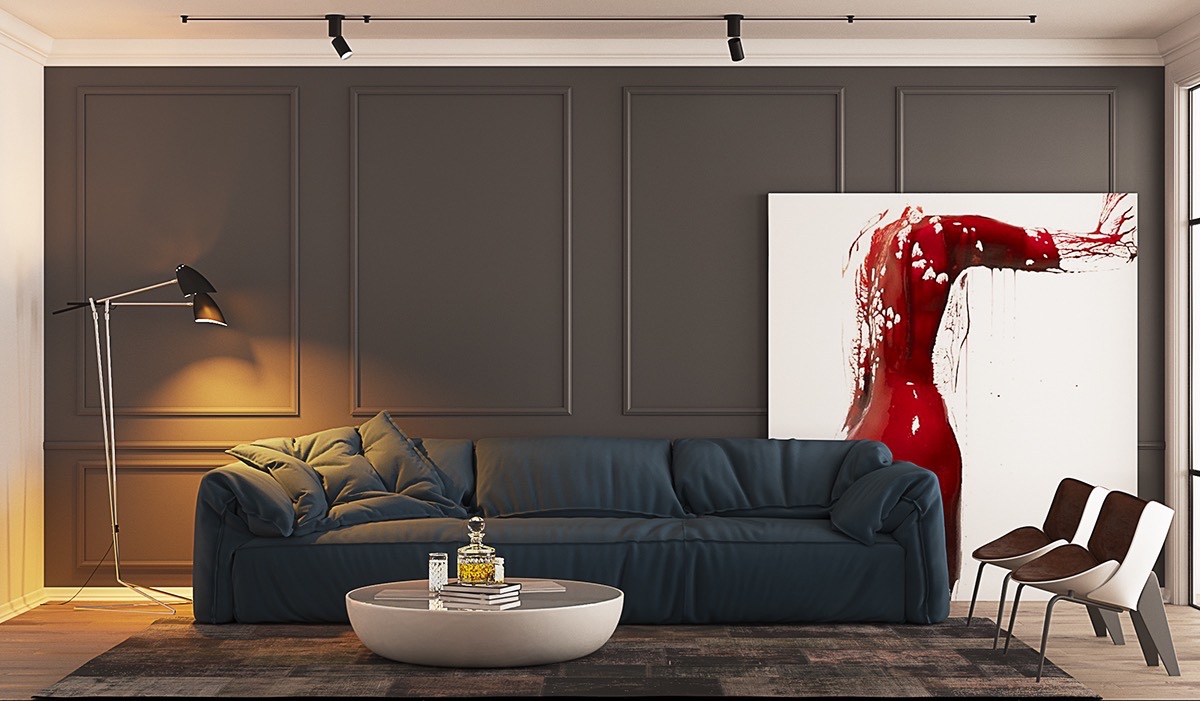
The red in this art seems to be spilling off of the canvas, creating a dramatic look leaned against this dark taupe wall.
ADVERTISEMENT
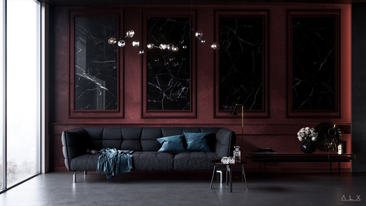
Panels of black marble framed within the wall creates a wall of mystery for this room.

With this white marble fireplace and platform, not much is needed. So, why not lean a wall of fish art. If you are working with a wall that you don’t want to anchor art to, try giving it a lean.
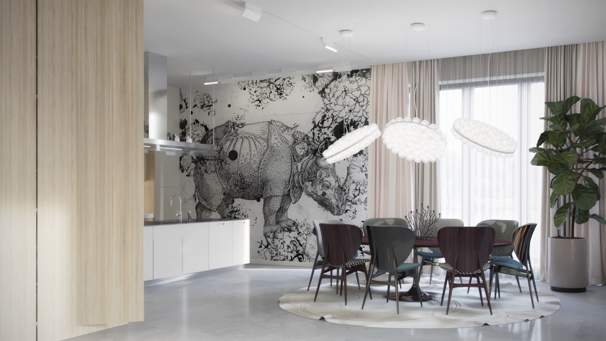
A contemporary nuetral dining room was completed with a rhino to fill an entire wall. Black and white art, with something meaningful to you, adds interest to the room without a lot of color if you are going for a monochromatic look.
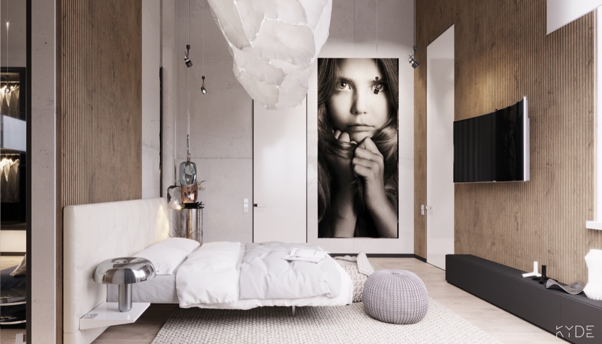
An oversized portrait hangs on this wall, simplicity at its best.
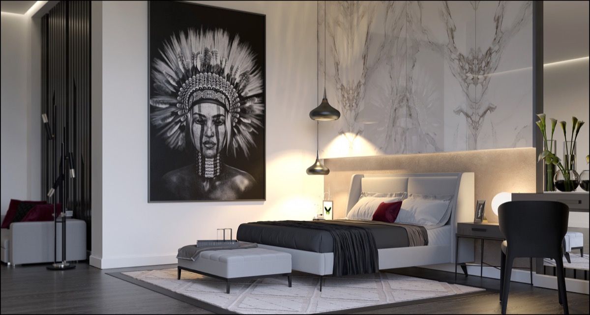
It may be suprising, but tribal art can be used in even the most modern of rooms. This monochromatic piece sits next to a marble wall.
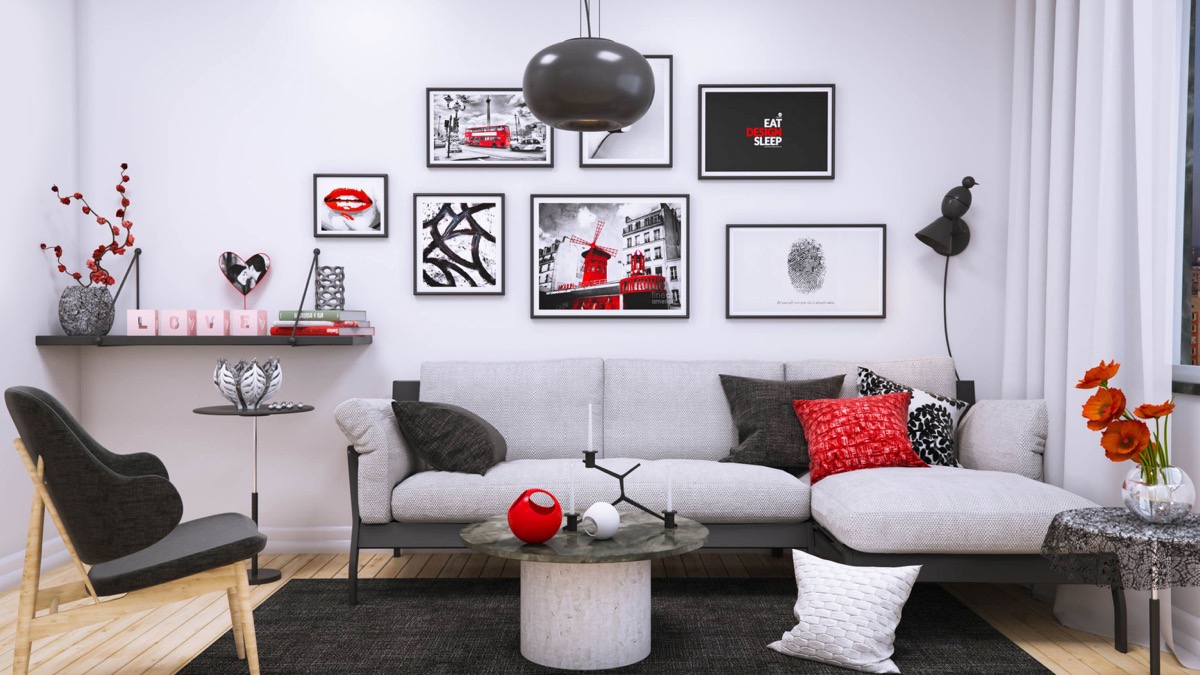
This effortless design of grey and black is enhanced by throw pillows and amusing art pieces in the same hues.
ADVERTISEMENT

This low back sofa and textured wall needed only a few simple pieces. The three panel swirl art in camo colors were used above the sofa adding color to the room.
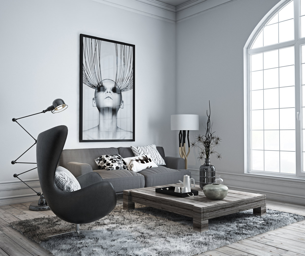
A dramatic portrait is used in this grey and white room, and is a perfect conversation starter.
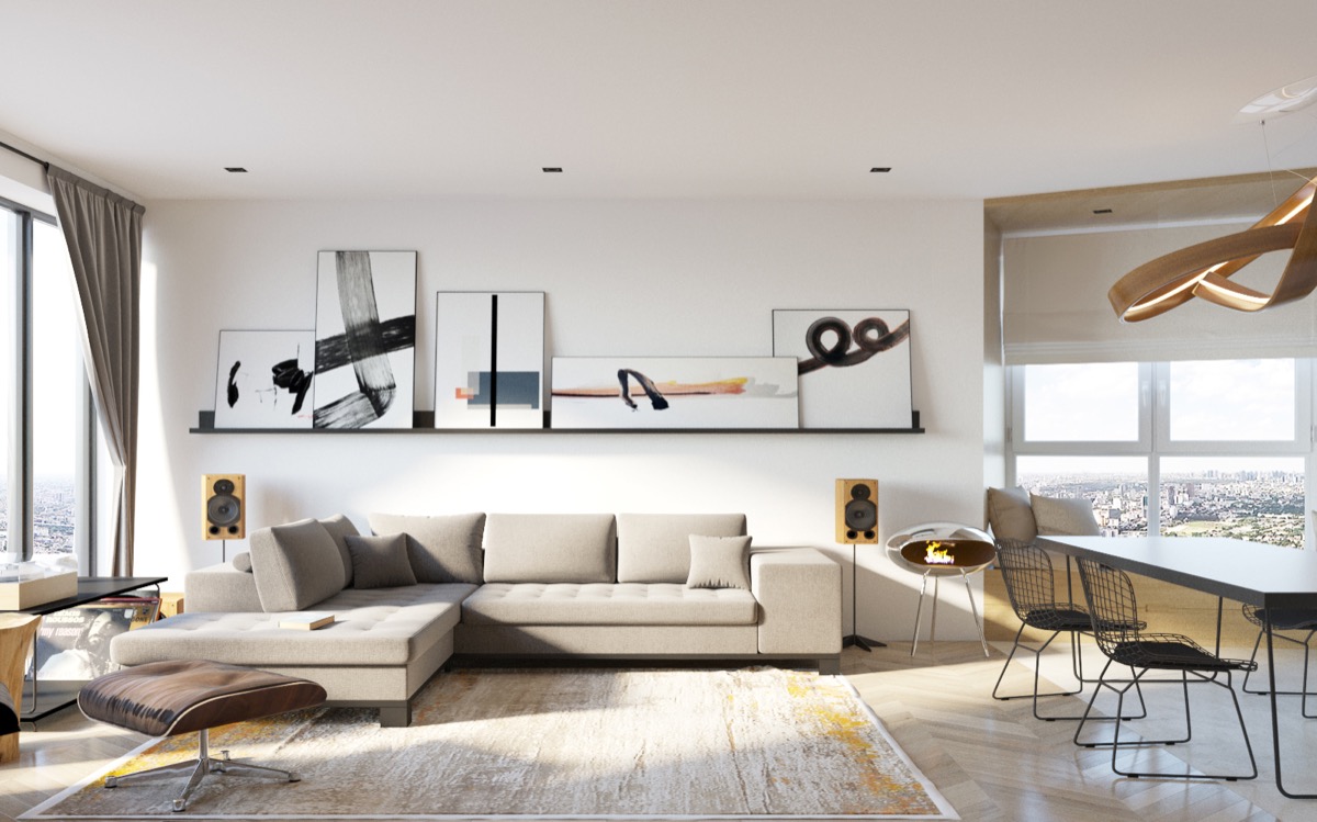
A shelf the length of the neutral sectional was used to display several abstract pieces, enlongating the room.
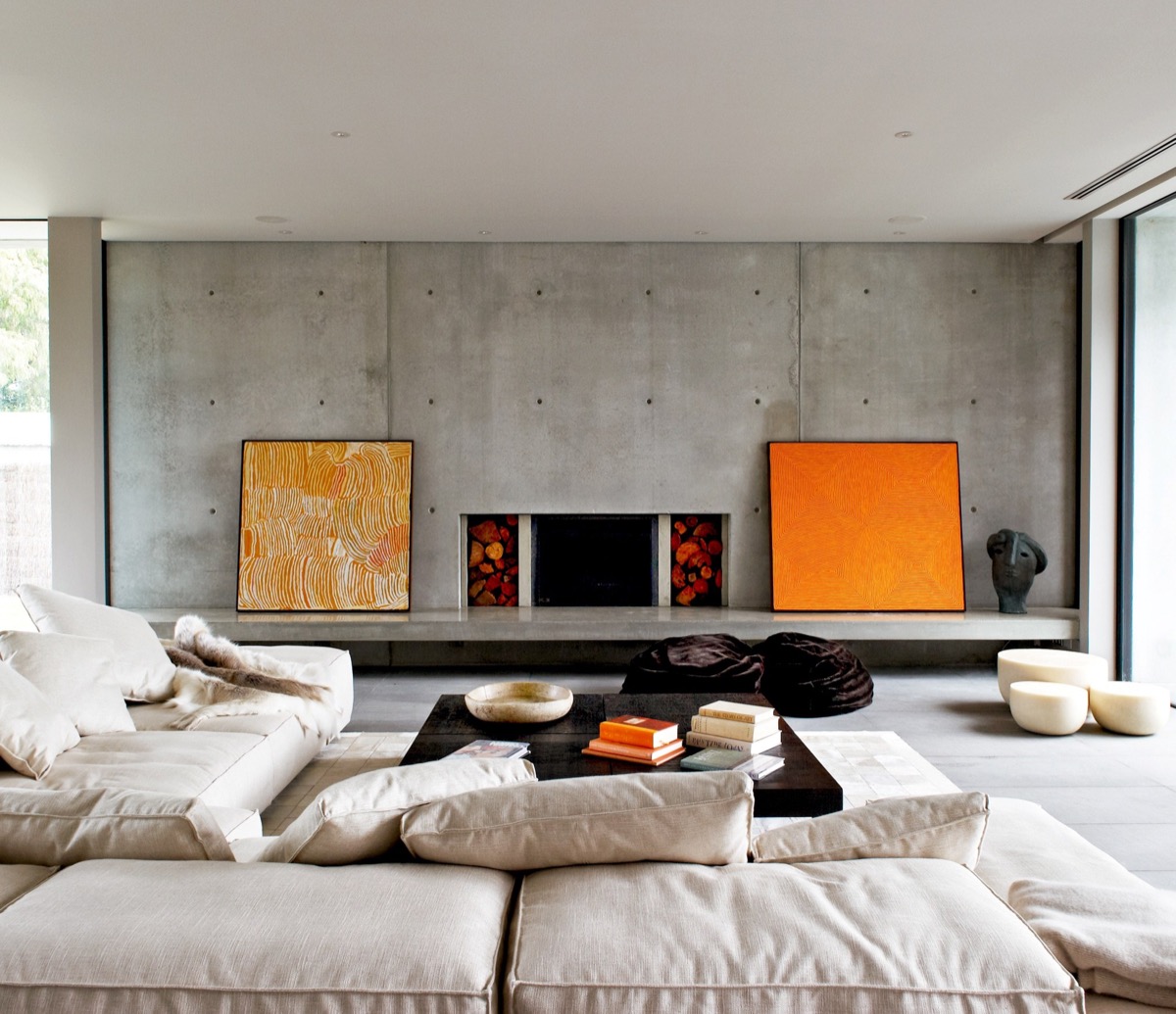
This textured concrete wall has two bright orange art pieces flanking the fireplace, adding color to a room that could appear cold without it.
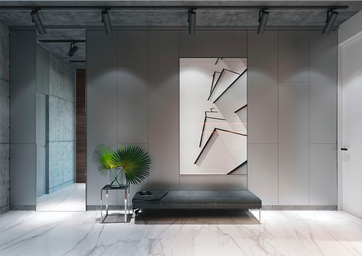
This foyer is reminiscent of a commercial space, but it is residential. The shades in the marble floor, and slate grey wall were picked up in this abstract piece.
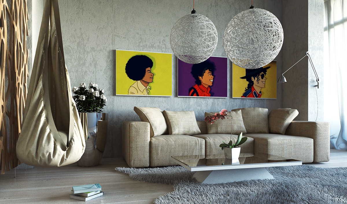
Your love for your favorite artist can be displayed. Here the different stages of Michael Jackson was used in colorful paintings in a achromatic room.
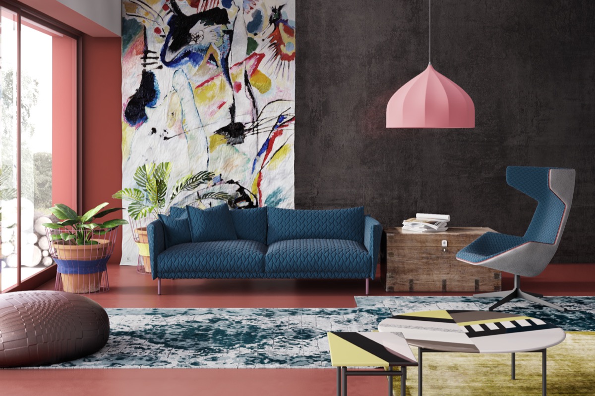
Color was used everywhere, the floors walls, furniture, and lighting. So why not incorporate all of those colors into one dramatic piece on the wall?
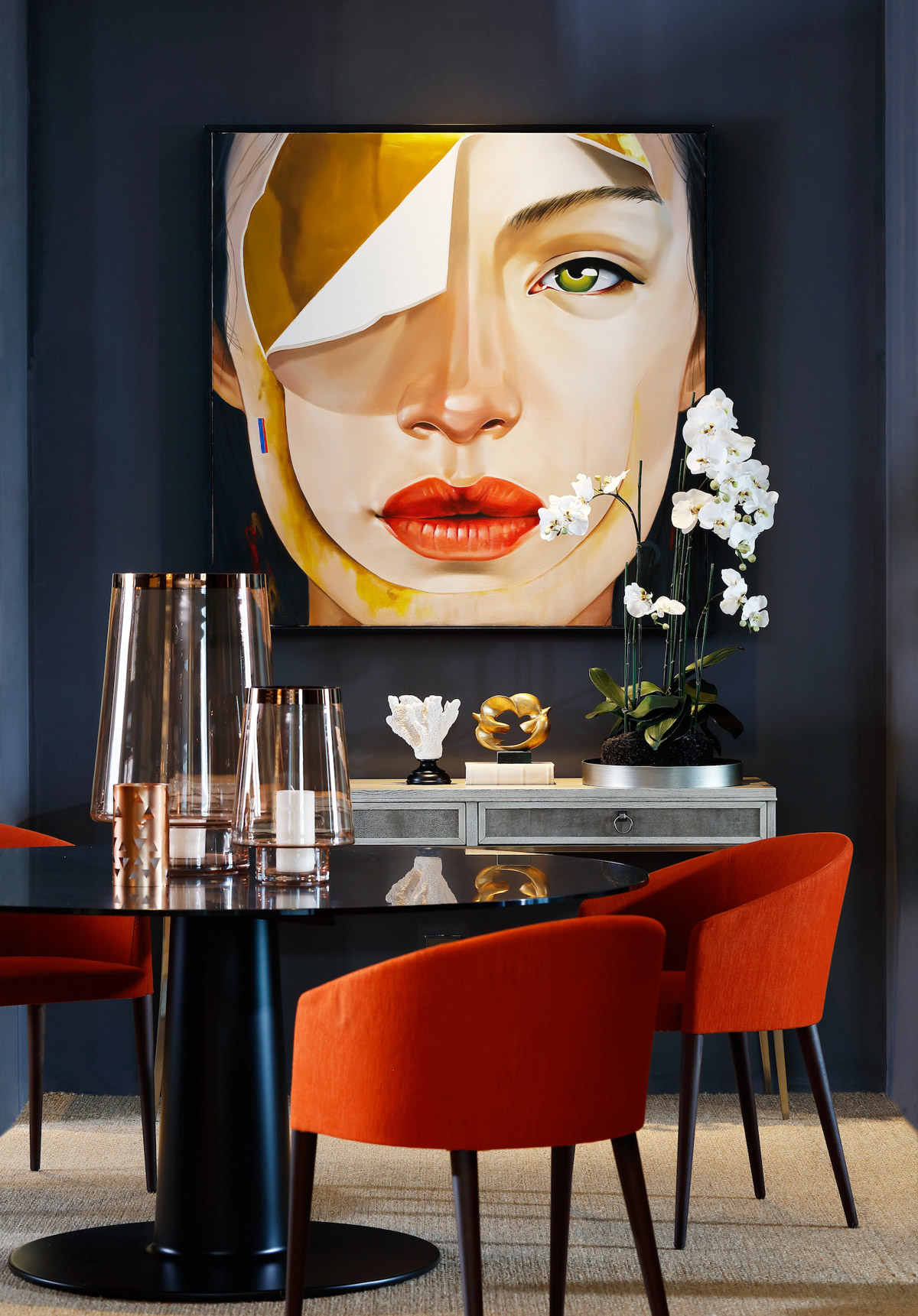
The alluring dining room of this Beijing home drips in opulence. This peeling face painting can mean several things and creates a way to start dinner conversation.
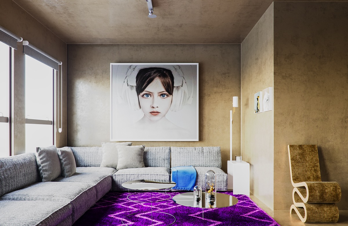
This textured wall and purple carpet started a great tale and is completed by the girl in white headphones on the wall.

In Grey and White Interiors , botanical prints give life to this room.
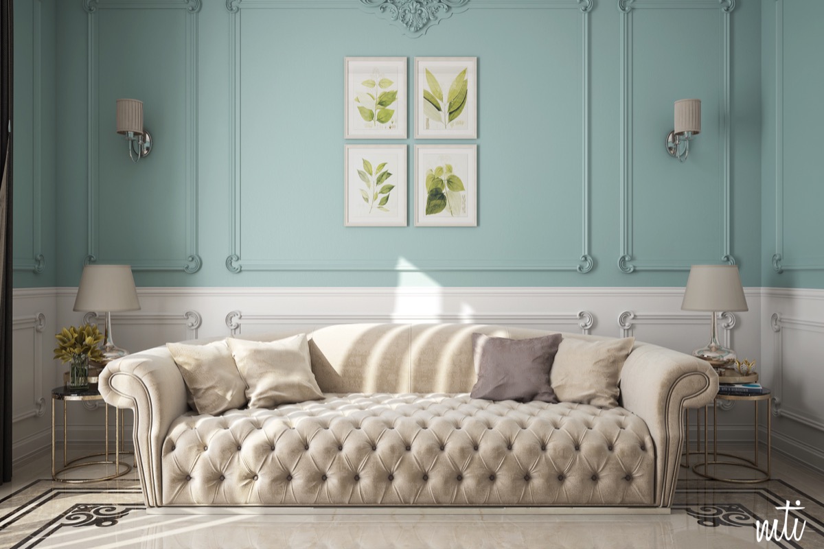
This traditional look in creme and blue uses botanical art prints. Find more here: Botanical Art Prints
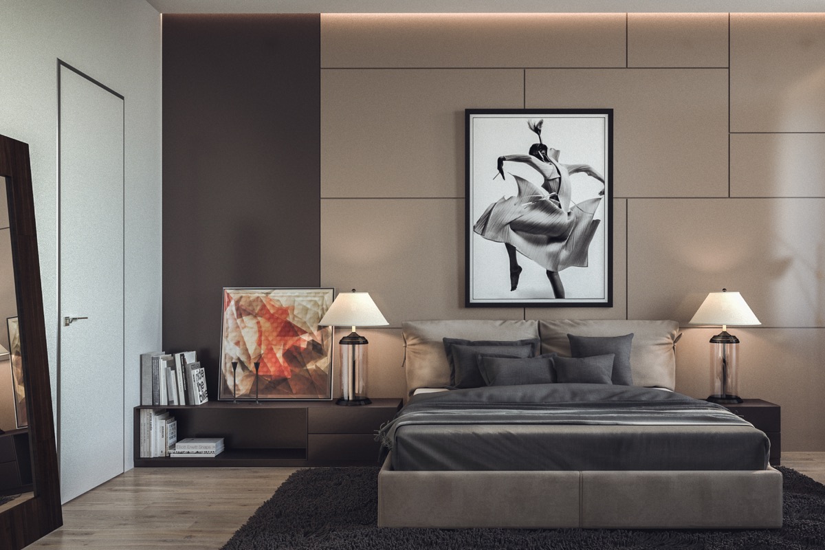
You don’t have to choose between monochromatic and lots of color, use both. This bedroom uses a fanciful dancing piece above the bed and an abstract piece in oranges and red on the night table.
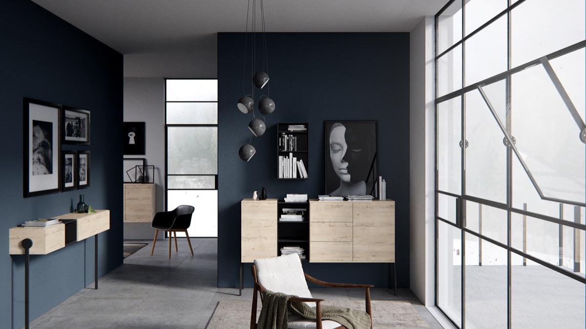
This black and white art is placed against a dark slate blue wall.
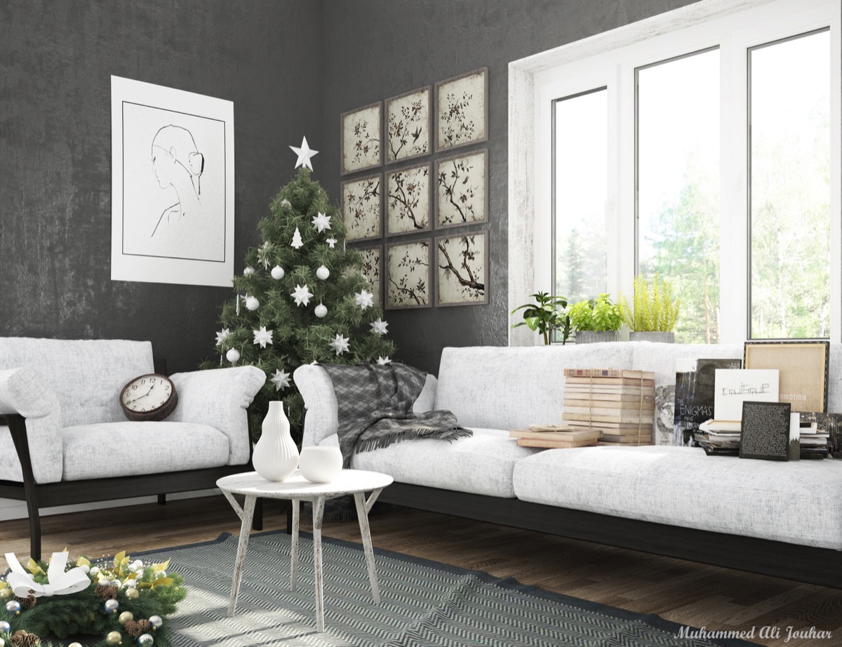
Use panel art on one wall and a single piece on the adjoining wall. It fills the space but doesn’t overwhelm it with large pieces.

Your art doesn’t have to be uniformed, in this room the work is placed at varying heights and creates a refreshing look.
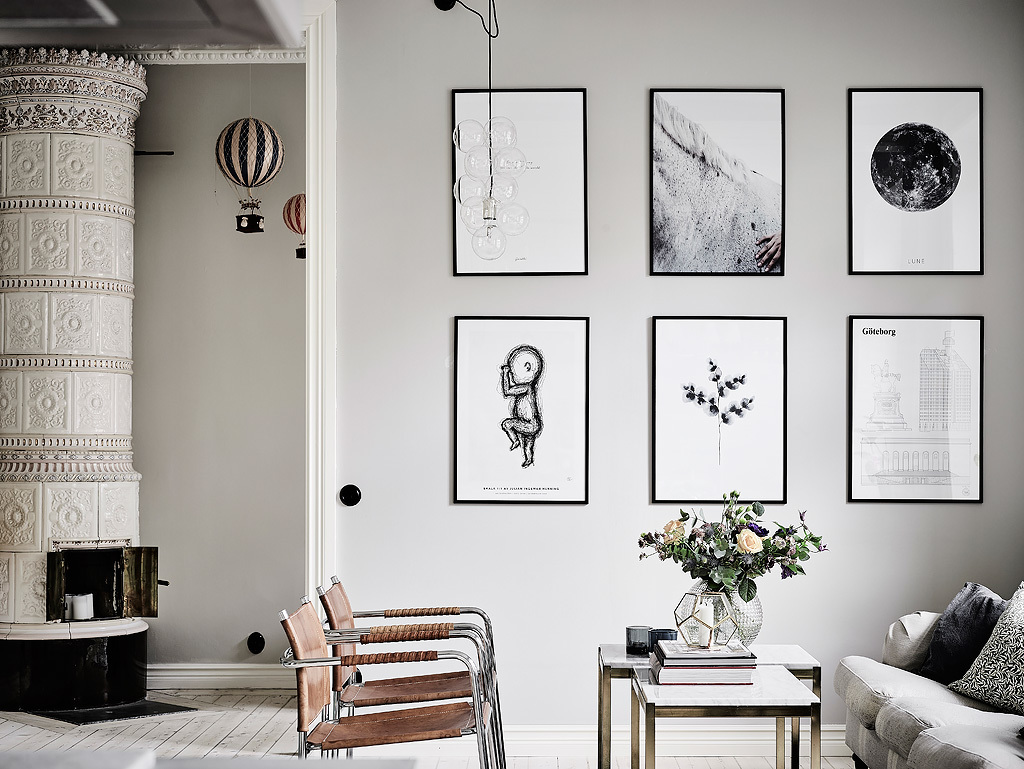
This straightforward minimalist style was enhanced by the artwork. Using various pieces together tell as story and share favorite pieces with visitors.
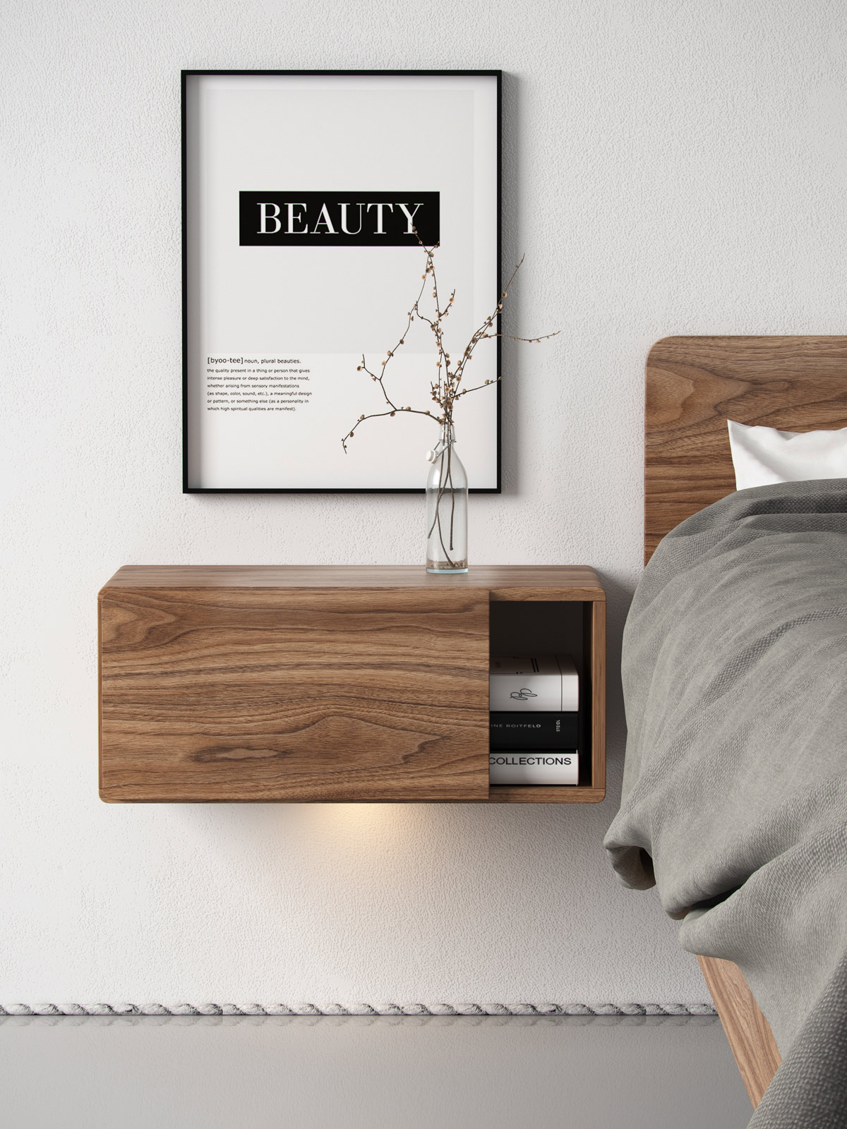
The artwork in this bedroom is as uncomplicated as its furnishings, use word art on your wall to make a statement.
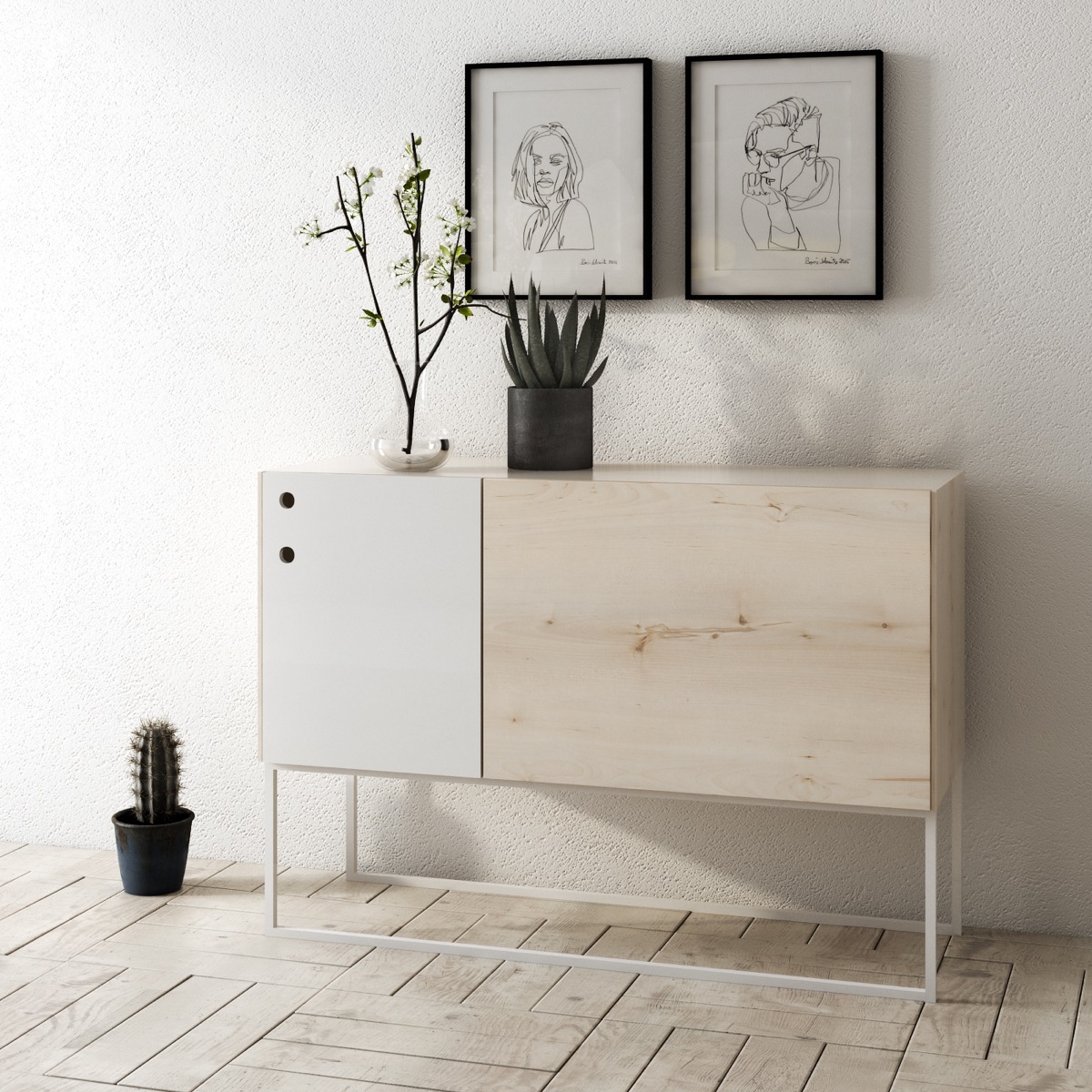
Artists renderings make for great wall art. Here two were paired together over a simple console table.
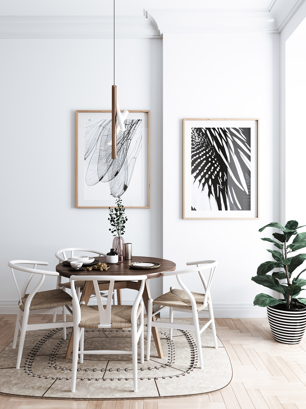
This art magnifies the beauty of wings and tells a story in two pieces in this Scandinavian Dining Room
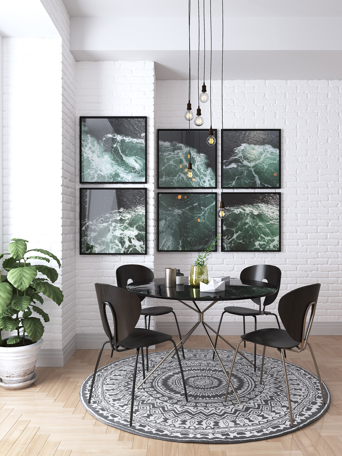
Create an atmosphere of peace and calm, here 6 photographs of the rushing water was used.

Clearly this is a city apartment using art to whisk the homeowner away to the mountains and oceans. Use art to take you to your favorite places.
 BUY IT
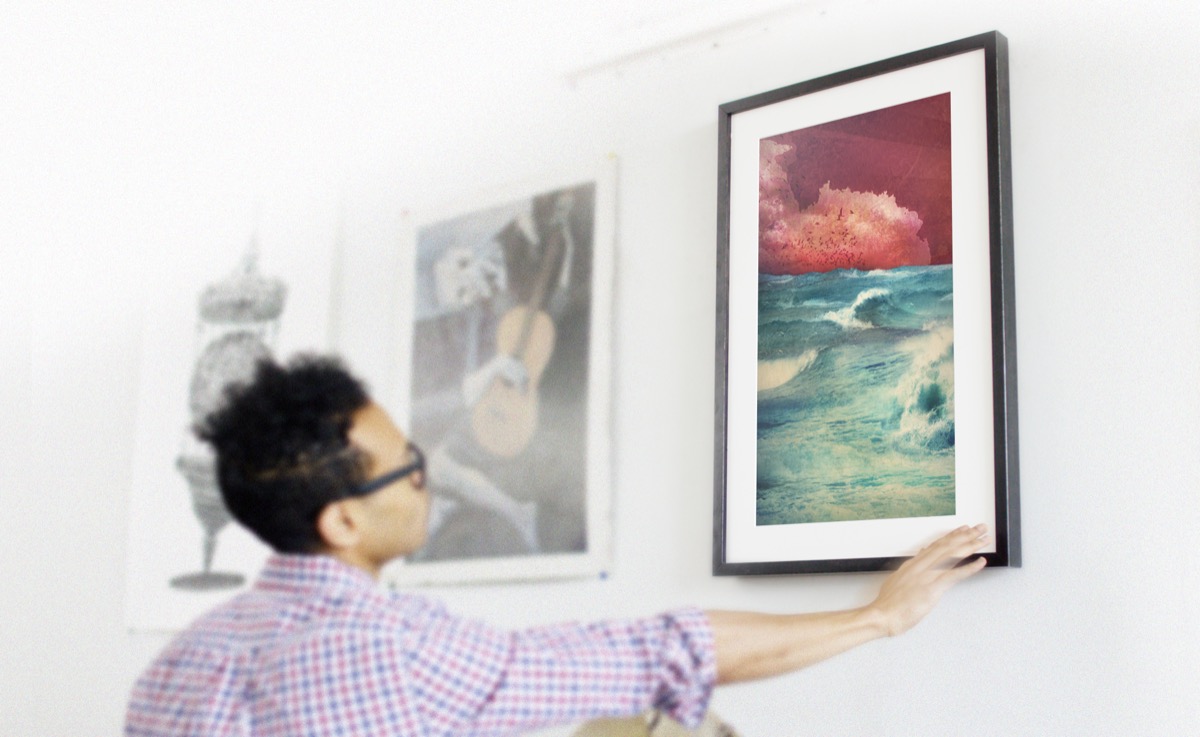
A new generation of digital art frames are gaining popularity. This digital canvas from Meural allows you to display and switch art at will with just a gesture of your hand. See it in operation below:
If you’re into architectural visualisation or environment work then it’s very likely that you will need foliage of some kind. Over the last few years Laubwerk have produced some of the best quality foliage packs around.
What makes them special is not just the excellent models and accompanying textures but the implementation. Not only doe they ship plugins for various host apps but the Laubwerk player also lets you dial in attributes for your plants, from age of plant to the season, with materials and meshes responding appropriately.
Now, Laubwerk have released their first shrub pack, as well as a new Maya player, bringing these top quality kits to an even bigger user base.
Not that long ago the foundry announced their new model for development of modo and now we are seeing the results of the second edition in this series, 10.1.
10.1 is solidly focused on modelling and brings to the table far more than can be talked about here but the highlights are some huge additions and improvments to MeshFusion, the versatile Boolean system. With similarities to Zbrush’s shadowbox it allows the user to create Booleans from different angles, making complex shapes far easier than traditional methods.
Also a big new feature, and one that joines forces with other areas of modo, is the procedural modelling system,. With many uses it’s hard to describe fully here but see it as a way of creating and editing models non destructively, with operators able to be freely moved, adjusted and animated.
10.1 is a big release so head to the product page to read more and see some of the demo videos.
The battle for rendering supremacy is raging away, with both GPU and CPU camps having good points to make. However understanding the benefits of one system over another is not always that simple but Chaos Group Labs have come to the rescue, with this in depth and best of all, free guide on how working with a GPU can make your life as a cg artist easier, or at least quicker.
Of course there’s a slant towards V-Ray but that is in some ways irrelevant. The pros and cons are the same and the authors have put together a really comprehensive guide, covering everything from compute power background and history to what the future could hold.
Default Cinema 4D installs don’t provide a way of easily connecting spline objects but Mike Udin, has the answer. His new Fast Spline Connect plugin, available from cgtools, makes it about as simple as any command can be.
At just $15 it’s impossible to resist if you ever work with splines and should really be a part of the standard feature set. Seeing as Cinema 4D has such a large user base we can certainly see this being a popular plugin.
If you are a fan of Autodesk software but your budget prohibited signing up tho their subscription service there’s some good news. The big ‘A’ have reshuffled their software suites into ne ‘industry collections’, which contain the same core products as before, although obviously not softimage, and they come out at a fairly substantial reduction in yearly cost (around $300 depending on your choices).
On top of this the new collections also sign you up to a new cloud service, for rendering, storage and other tools like the character builder.
There will no longer be the option to buy a perpetual license however, so if you really need to use the software plan ahead.


VRay 3.00.01 for Maya 2015 | 160 MB
Info:
V-Ray 3.0 for Maya focuses on artist productivity and delivers a powerful new set of features and improvements to speed up lighting, look development and rendering workflows.
Built to meet the creative demands of CG artists and modern production pipelines, V-Ray 3.0 for Maya is a full suite of physically-based lighting, shading and rendering tools tightly integrated into Autodesk Maya.
Faster Ray Tracing and Rendering Performance – V-Ray 3.0 includes a number of overall speedups, and the new optimized ray tracing core performs significantly faster.
Faster Feedback – The new Progressive Image Sampler delivers instant feedback to artists and makes lighting and look development quicker and more intuitive.
More Powerful V-Ray RT – New in V-Ray 3.0, V-Ray RT renders directly in the Maya viewport and supports final frame rendering and animated sequences.
Advanced Characters and Creatures – Improvements to character and creature workflows include optimized Hair and Fur, improved Subsurface Scattering and a new VRaySkinMtl shader.
Buy here: http://www.chaosgroup.com


http://uploaded.net/file/50jdszgc/vray_adv_30001_maya2015_x64.rar

http://rapidgator.net/file/9f208f51a8c5dc1841eecfd5bc3ba79d/vray_adv_30001_maya2015_x64.rar.html

http://nitroflare.com/view/B62736BC0E0661B/vray_adv_30001_maya2015_x64.rar
V-ray 3.30.05 For 3ds max 2014 – 2015 – 64 bit
Render most scenes up to 20-50% faster with V-Ray 3.3 for 3ds Max! V-Ray 3.3 for 3ds Max introduces new variance-based adaptive sampling for quick setup, uniform noise distribution, and higher quality images – with less dependence on settings for lights and materials.
Variance-based adaptive sampler (VBAS)
Better sampling of dark areas and faster sampling of overbright areas
More consistent noise detection
Final image quality is less dependent on materials and lights settings
Improved alpha channel sampling – especially in scenes with depth of field and motion blur
Works in bucket and progressive rendering modes
http://rg.to/file/695d48a7eee528ae7d9c0ccaff9f3b77/VRAY33053DSMAX201415.part1.rar.html
http://rg.to/file/24ed9dd7777b39660fba584eef3c5648/VRAY33053DSMAX201415.part2.rar.html
http://rg.to/file/4b3374b260fec3610b2b5a8523bc6abe/VRAY33053DSMAX201415.part3.rar.html
http://rg.to/file/08bcf3ae60f60bc9af18c4f3b0131dad/VRAY33053DSMAX201415.part4.rar.html
http://ul.to/fwjfxqpb
http://ul.to/ijzougiz
http://ul.to/wagr0qv1
http://ul.to/odyq1fzt
http://nitroflare.com/view/E3DBC82F35470B7/VRAY33053DSMAX201415.part4.rar
http://nitroflare.com/view/DC8C4DC51C32AC6/VRAY33053DSMAX201415.part1.rar
http://nitroflare.com/view/8139AB438D2213C/VRAY33053DSMAX201415.part3.rar
http://nitroflare.com/view/15B1E0A868BFCA5/VRAY33053DSMAX201415.part2.rar

Conform is a compound object created by projecting the vertices of one object, called the Wrapper, onto the surface of another object, called the Wrap-To. There is also a space-warp version of this function; see Conform space warp.
 Create panel >
  (Geometry) > Compound Objects > Object Type rollout > Conform
Conform fits the road to the surface of the hills.
Because the space-warp version is somewhat easier to use, it’s a good idea to read that topic first, try the example, and then return here. This topic provides additional methods of projecting the wrapper vertices.
Example: To create a Conform object:
Create panel, with (Geometry) active, choose Compound Objects from the drop-down list. On the Object Type rollout, turn on Conform.
The list windows display the two objects, and the compound object is created with the Wrapper object conforming to the Wrap-To object. (In the example, the sphere is wrapped into the shape of the box.)
To project a road onto terrain:
An instance of the terrain object is created, with the same object color as the road.
 Vertex Projection Direction group, choose Use Active Viewport, and click Recalculate Projection.
This hides the instance of the terrain so you can clearly see the road projected onto it.
The Parameters rollout Wrapper Parameters group Standoff Distance value sets the number of units by which the road sits above the terrain along the world Z axis.

Displays the name of the selected Wrap-To object.
Click this button, and then select the object to which you want the current object to wrap.
This option lets you specify how the Wrap-To object is transferred to the Conform object. It can be transferred either as a reference, a copy, an instance, or it can be moved, in which case the original is not left behind.
Contains all parameters for the Conform object.

Provides a list window and two edit fields that let you navigate the compound object and rename its components.
Lists the Wrapper and the Wrap-To objects. Click to select an object in the window so that you can access it in the Modifier stack.
Lets you rename the wrapper object within the compound Conform object.
Lets you rename the Wrap-To object.

Choose one of these seven options to determine the projection of the vertices.
The vertices are projected away (inward) from the active viewport.
Recalculates the projection direction for the active viewport. Because the direction is initially assigned when you pick the Wrap-To object, if you want to change viewports after assignment, click this button to recalculate the direction based on the new active viewport.
Lets you use the local Z axis of any object in the scene as a direction. Once an object is assigned, you can alter the direction of vertex projection by rotating the direction object.
Click this button, and then click the object you want to use to indicate the direction of the projection source.
Displays the name of the direction object.

Provides controls that determine how far the vertices are projected.
The distance a vertex in the Wrapper object will move from its original location if it does not intersect the Wrap-To object.
The distance maintained between the vertex of the Wrapper object and the surface of the Wrap-To object. For example, if you set Standoff Distance to 5, the vertices can be pushed no closer than 5 units from the surface of the Wrap-To object.
When turned on, only the selected vertex sub-objects of the Wrapper object are pushed. When turned off, all vertices in the object are pushed, regardless of the Modifier stack selection. To access the Modifier stack of the Wrapper object, select the Wrapper object in the list window, open the Modifier stack, and select the base object name. At this point you can apply a Mesh Select modifier, for example, and select the vertices you want to affect.

The items in this group determine when the projection for the compound object is recalculated. Because complex compound objects can slow performance, you can use these options to avoid constant calculation.
Recalculates the projection.
When on, hides the Wrap-To object.
Determines whether the shape operands are displayed.


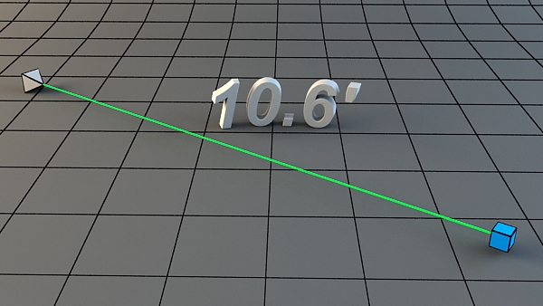
In this quick tip, Alex Martin introduces you to two features of 3D Studio Max that many new artists overlook, a correct unit setup and the ever handy tape tool. Working with a correct scene scale is extremely important, especially when it comes to multiple artists working on the same scene, or when recreating accurate lighting for a project. This quick tip will give you a few tips for setting up your units system correctly, and provide a practical example for measuring the distance between objects using the tape tool and how this applies when working with Z-Depth.
Whenever we create a primitive object in 3ds Max, it shows its dimensions without any proper unit by default. For example, I have created a box in the viewport and you can see there is no unit setup defined for its dimensions (Length, Width and Height). However these dimensions have some values, but we don’t know what exactly these are; meter, feet, inches, centimeters or something else?
The majority of 3ds Max users just start working this way, and this is indeed a fatal tendency. If you’re working on an architecture or industrial project, or anything which requires a correct unit setup, then you must take care of it.

Not working with a correct unit setup can create lots of other problems. Let’s look at it through an example. Say, there are two users A and B, working in 3ds max on two different machines and both are working without setting up the correct unit order. User A has created a biped (scene 1) and user B has made a car (scene 2).

Now, after merging both projects together (scene 3), it shows the real problem. In scene 3, you can see the ratio mismatch clearly. The biped is too big for the car. This happened, because both users were working without setting up the correct unit order. If they had used the unit setup before, this problem could have been avoided.

Now, let’s see how to work with the correct unit setup. Open 3ds Max and first of all go to the Customizemenu. Here click on the Units Setup… option.

This opens Units Setup window. Here click on the System Unit Setup button to open the System Unit Setup window. By default, it shows 1 unit = 1 inch.

This means if you draw a box in the viewport, its dimension values are in inches by default. So in this example, a Length value of 40.0 means 40 inches and so on.

Now let’s go back to the Units Setup window. You can choose here a metric unit system also. Just turn on the Metric radio button and select any of the available units (meters, centimeters, kilometers etc). Then click on the OK button.

Now create a new Box in the viewport, and you’ll see its dimension values are in meters now.

You can change the unit system to US standard also. You can see I have changed the system unit to Feet/ Inches and now the same box’s dimension values are displaying in feet/ inches. So this is the way to get a correct measurement in 3ds Max.

Now let’s see how we can use unit setup in a different case. I have created a biped in the viewport. The question is, how to determine the exact height of the biped? Since the biped doesn’t have any dimension values, we need to apply a trick to know the height of the biped.

There is a simple trick to set the proper height of the biped. Create a Box of the same height beside the biped. Now check the height value of the box. It shows 16 feet and 5 inches. This means the biped has the same height as well. So this is the trick to determine and setup the proper height of a biped.

Now let’s see how to determine the proper distance between two objects in 3ds Max. I have created two objects in the viewport, and now we have to get the exact distance between the two.

To know the distance between objects, we’ll use Tape tool. Click on the Helper icon and then select theTape tool.

With the Tape tool selected, first click on the starting point, don’t release the mouse button and then click on the end point. The starting point of the tape tool is called the head/ tape and the end point is called the tail/ target. The connecting line in green between the head and tail represents the current distance.

If you select the head of the Tape tool, you can see the exact length or distance between the head and tail points.

If you turn on the Specify Length option, you’ll see the Length value gets changed and the green line of the tape tool exceeds a bit.

You can easily set it correctly by the spinner for the Length parameter.

Let’s see through an example, how the tape tool helps in Z-Depth channel extraction. Press the F10 key on the keyboard to open the Render Setup window. Here go to the Render Elements tab and click on Add. This opens the Render Elements sub-window. Here select Z Depth and then click on OK.

Inside the Z Depth Element Parameters, there are two options, Z Min and Z Max. If you want the correct Z Depth value, then you must know the correct Z Min and Z Max values, which are actually the distances from the camera focus to the target objects.

So you can see how important the measuring tools are in 3ds Max. I hope you have enjoyed this quick tip tutorial.

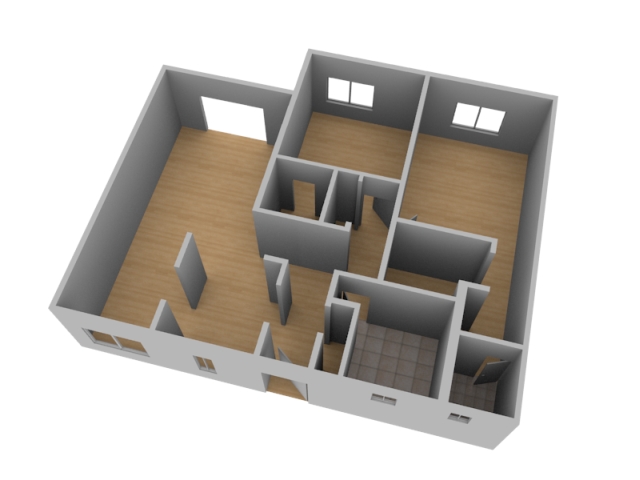
In this tutorial you’ll learn how to create a 3D floor plan model from an 2D architectural drawing. Karan Shah will show you some simple, yet effective techniques for constructing the walls, windows and doors following a basic interior schematic in Blender. With the model complete we’ll add materials and textures, and do a final render of the scene.
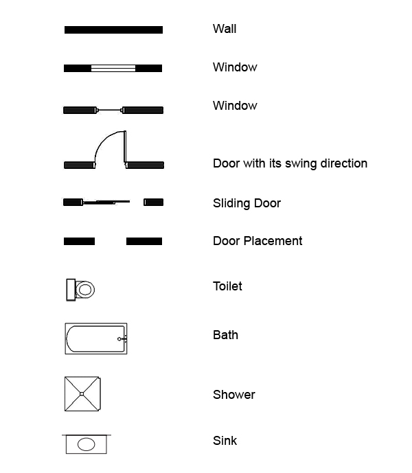
Floor Plans are simply a drawing or a diagram showing a top view of a site layout. You can see the picture to understand the meaning of some basic symbols used. More can be found
here (pdf).
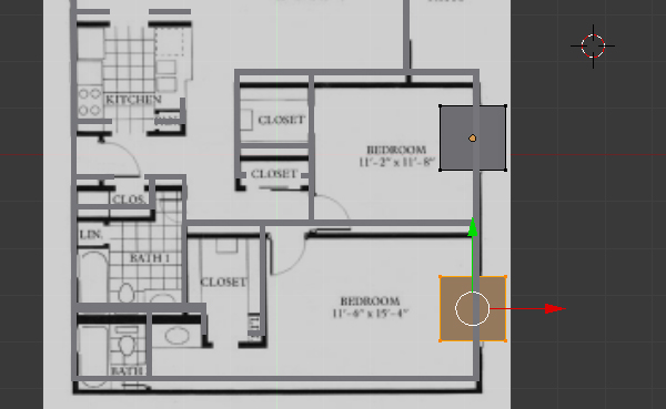
In a new file, select all objects with the ‘A’ key and press ‘Del’ to delete them. Press ‘N’ to bring up our View properties. In the Background Image Panel, add your reference image. Here I have used image courtesy ofLiamKeiranCooper Ltd who kept the picture in public domain.

Press ‘7’ on the NumPad to get into the Top view. Here you can see the background image. The view must be set to ‘orthographic’ in order to see the image. You can toggle between the ortho and perspective views with the ‘5’ key on the Numpad. Press Shift+A and add a Plane.

With the Plane selected, press ‘TAB’ to get into ‘Edit’ mode. Select all the vertices with the ‘A’ key, or press ‘B’ to drag select them. Press ‘G’ and move them to the top left corner. You toggle the viewport shading between solid and wireframe with ‘Z’ key. Press ‘S’ and move the mouse to scale them down to fit the width of the wall (as shown below.)


Now we will cover all the black solid areas i.e. the walls. This will include the windows as they are part of the walls and will be added later. Any type of door whether it’s a slider or normal, is to be left out. Select the bottom two vertices (press ‘B’ to drag select or Hold ‘Shift’ and Right click for multiple select.) And move them down just before the wall turns left. Press ‘E’ and extrude the wall again until you reach the edge.
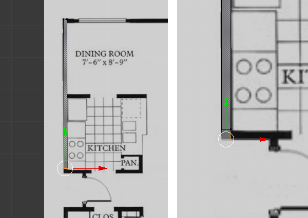
Select the right two vertices and press ‘E’ to extrude, and match the reference.

Now, in order to extrude out a face from the middle, we need to add an Edge Loop. Hover your mouse over the face, and press ‘CTRL+R’ and Left Click to confirm. Move the mouse up and down and then Left click again to confirm its position.

Create another edge loop just below the previous one using the same method, matching the width of the wall to be extruded.
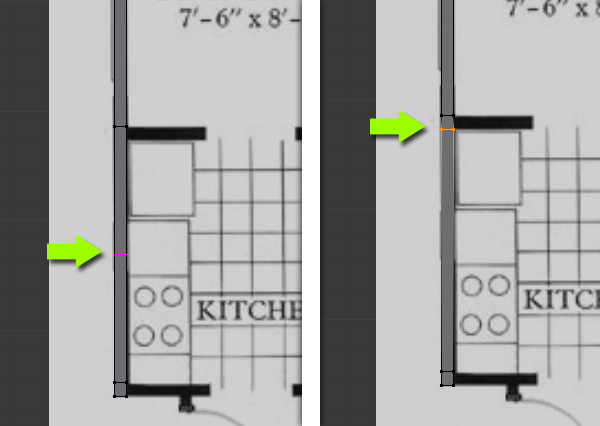
Select the two vertices and extrude the wall.

Create another edge loop on the corner and extrude the right edge.

Using the techniques above (extrude and edge loop division) fill all the solid black lines of the reference image with the mesh.

To start a new separate wall, duplicate the last edge and then start extruding it. Select the last edge and press ‘Shift+D’ to Duplicate it, and left click to confirm. Move it with the Move control widget or press ‘G’ key of the keyboard. And continue extruding the mesh along to match the reference.

Complete the walls with the techniques you learned from above steps.

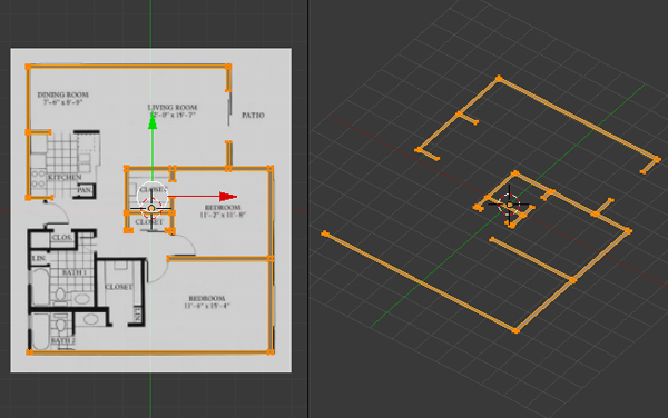

After completing the wall, select all the vertices and then press ‘E’ to extrude them along the Z axis. Now we see that the structure is taking shape. The height should be equivalent to a door.

Press ‘Ctrl+TAB’ and select ‘Edge’ in the mesh select mode menu. Select the top two corner edges of a door (hold shift + right click to multiple select) and press ‘F’ to make a Face between them. Do this for all doors. Refer to your image and always check from all views.


Press ‘3’ on the Numpad to get into side view, and Press ‘Z’ to get into wireframe view so that we can see all the vertices behind are visible and can be selected. Press ‘B’ to drag select all the top vertices or edges, then Press ‘E’ to extrude them. This will reach the final height of the wall.


Now we will place the windows. Press ‘TAB’ to get out of the Edit mode, and in object mode, press ‘Shift+A’ and add a ‘Cube’. In the Top view, size (press ‘S’ to scale) and place it where the window is on the reference image.

In the side view, the top part of window should align to the top of door. Press ‘TAB’ to enter into the edit mode to adjust the vertices. Adjust the bottom height of the window too. The width of the cube should be such that it should be half inside and half outside. See image below.

Select the Wall mesh with Right click, and in the Properties button window, click on ‘Object Modifiers’.

Click on ‘Add Modifiers’ and select ‘Boolean’.

In the Boolean modifiers panel, select ‘Cube’ in the Object, and ‘Difference’ under ‘Operation’.

To see the effect – Select the cube and press ‘H’ to hide it. You will see that there is a “hole” in the wall the size and shape of the cube. Press ‘Alt+H’ to ‘Unhide’ the Cube.

Now select the Cube (window) and in the ‘Edit’ mode, select all the vertices and press ‘Shift+D’ to make a duplicate. Place this new cube in the location of the next window.
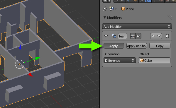
Now press ‘Tab’ to get out of ‘Edit’ mode, and select the Wall mesh and press ‘Apply’ in the ‘Boolean’ Modifier panel. The holes are now part of the geometry.
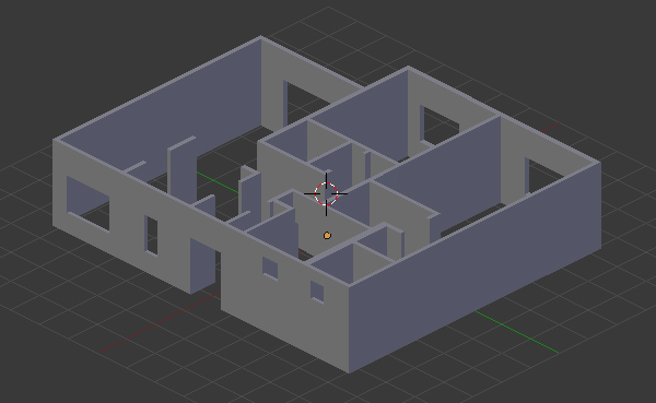
Move the Cube to see the windows.

Similarly create all the needed windows with this Boolean modifier. Try doing them one by one, adjust the size and position of the cube according to the specific window.
Now we will create the Floor. In ‘Object’ mode and in the Top view, press ‘Shift+A’ and add a ‘Plane’. Press ‘Tab’ to get into ‘Edit’ mode and adjust the vertices accordingly so that it covers the walls. Create Edge Loops or Extrude the edges where necessary.


Make sure that there are no gaps between the edges of the floor and walls. Also in the Side view, move the floor down so it’s aligned with the bottom of the walls.

To make doors, add a new’Cube’. And in ‘Edit’ mode, press / on the Numpad for Local view (this will show only the selected object.) In the Top view, Move or Scale the vertices to give it a nice shape. Refer to the image for the height and width.

In the Top view, and in ‘Edit’ mode. Move all the vertices of the door along the Y axis, so that the center point of the object (orange dot) should be at the corner (see image.) This will set the transform orientation of the object from that corner. Press ‘TAB’ to get out of edit mode and then press’R’ to Rotate and see the difference.

While in the edit mode, add a new ‘Cylinder’. Rotate and scale it down to create the doorknob (you can add more details if you like.) Press ‘TAB’ to get out of edit mode.

With the help of the reference image, place the doors in the correct positions (press ‘Shift+D’ to make duplicates.)

Now we will create the window frame. Start with another new ‘Cube’, and press ‘TAB’ to enter into ‘Edit’ mode. Press the ‘Z’ key to toggle wireframe view, so that we can select the back vertices too. Press ‘3’ on the Numpad to get into side view and then extrude the faces as shown in the image to make the window frame. Press ‘TAB’ to exit out of edit mode, and press / on the numpad again to get back to the scene.

Scale and place the window frames on the walls. Make duplicates and place them according to the image.

Now we will add a texture to the floor. Right Click on the Floor object to select it. And in the Properties window, click on the ‘Materials’ Icon. Add a New material and name it ‘Floor’, increase the ‘Diffuse’ intensity and reduce the ‘Specular’ intensity.

Next we will add an image to the floor. (I got mine from Here.) Click on the ‘Texture’ icon next to the Material icon, and then Click on the ‘New’ button. Select ‘Image or Movie’ for the Type and in the Image panel, click on “Open’ and browse for the image.

You can preview the texture in the 3d View. Press ‘N’ to bring up the ‘View Properties’ and in the ‘Display’ panel, select GLSL in the ‘Shading” menu (you’ll need to add some lights in the 3d view to see the texture.) Now press ‘N’ again to hide the view properties panel.

Back to the Image Texture properties, scroll down to the Mapping Panel and increase the Size of X and Y to5 or 6 depending upon your image file.

Now to add a separate floor to the Bathrooms, we will add a new ‘Plane’ and adjust it’s dimensions and place it just above the wooden floor so that it’s hidden.

Apply an image, just like we did on the floor (I got mine from Here.) Duplicate the Plane and adjust it’s geometry by scaling and extruding for the second bathroom.


Select the walls and add a New material to them. Choose any color and Increase the ‘Diffuse’ intensity and set the ‘Specular’ to 0.0

Similarly assign the materials to the windows and doors. You can assign the same material to any object by selecting the material from the list.

Now we will prepare the scene for rendering. Make sure you are Not in ‘Edit’ mode (press ‘TAB’ to toggle Edit mode on/off.) Press ‘7’ on the Numpad to get into the Top view, then press ‘Shift+A’ to add a camera.

Rotate and place it however you like. Press ‘0’ on the Numpad to get into camera view.
Click on the ‘World’ settings and change the ‘Horizon Colour’ to white, then turn on ‘Ambient Occlusion’ and in the ‘Gather’ panel, increase the samples to 16. In the 3D view delete any lights if they exists.

Click on the ‘Render Settings’ button in the property window, and change the Dimensions (resolution) to your desired size. Down in the ‘Output’ panel, choose the file format for your render.

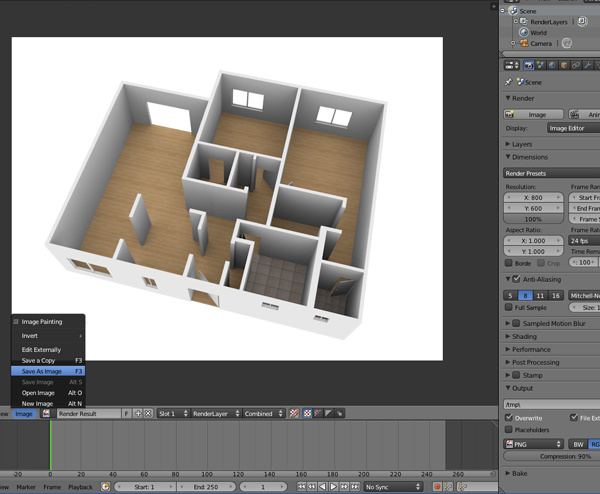
Press ‘F12’ or click on the ‘Image’ button in the render panel. Press ‘F3’ or click on ‘Image > Save image as‘ to save the image.
Your 3D Floor map is now ready!
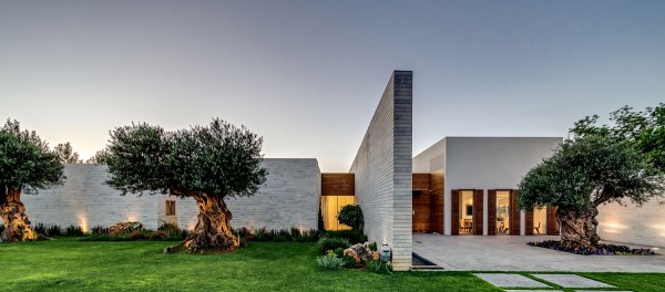
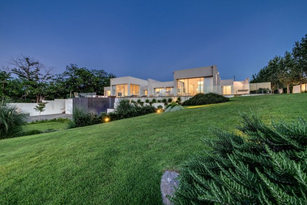
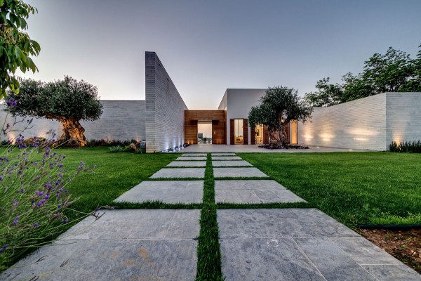
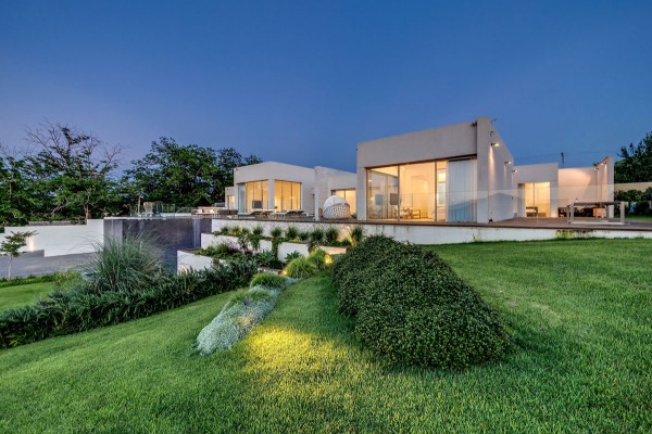
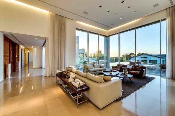
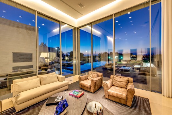
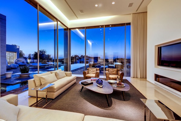
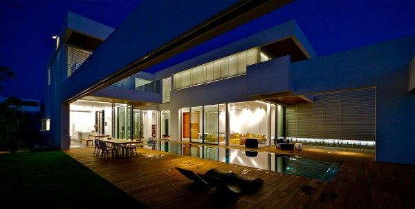
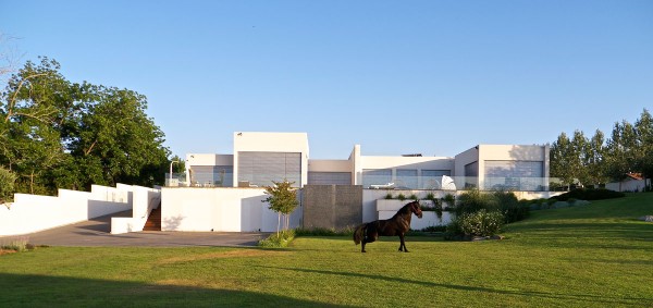
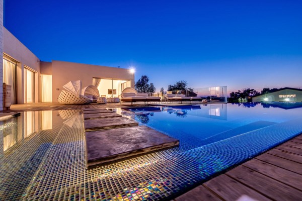
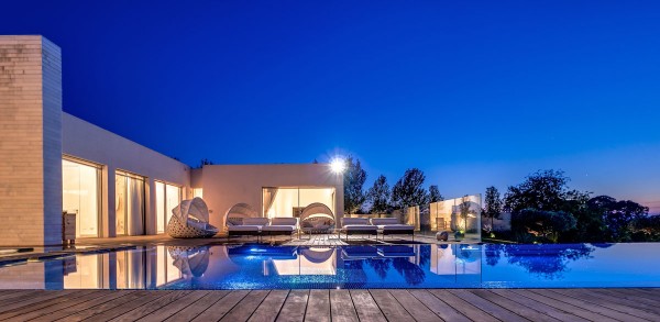
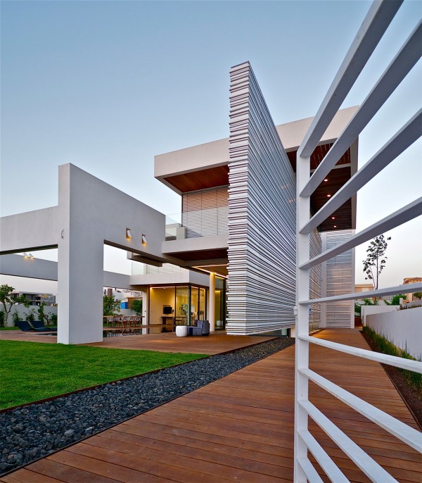
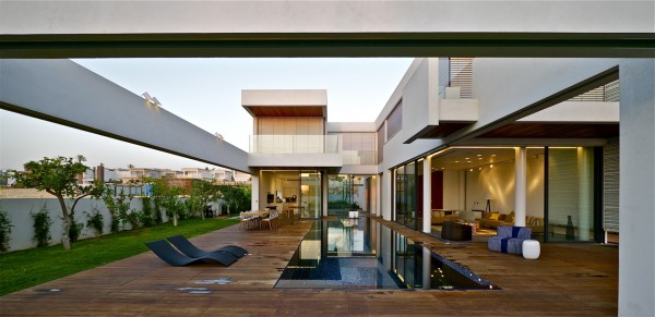
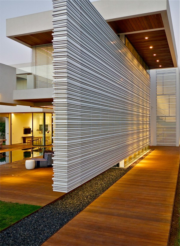
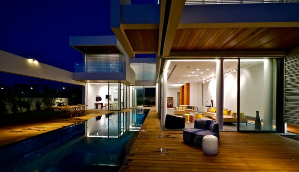
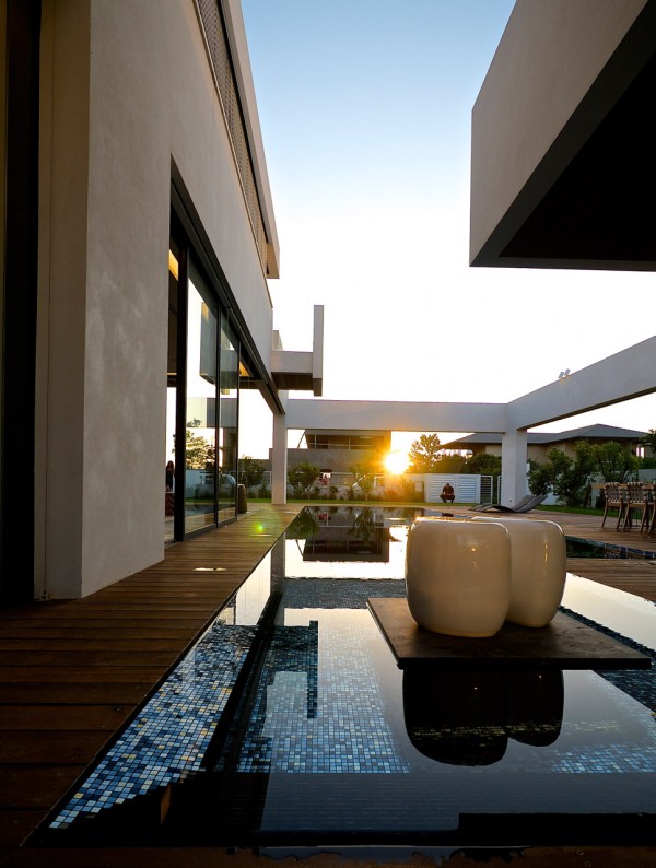
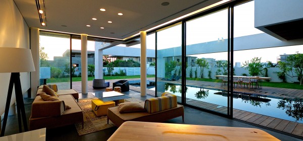
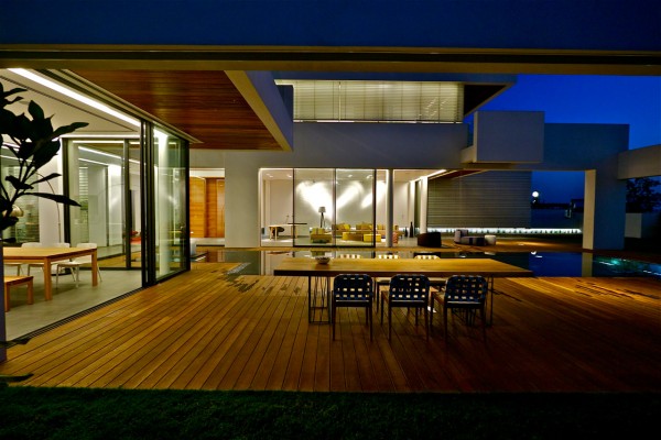
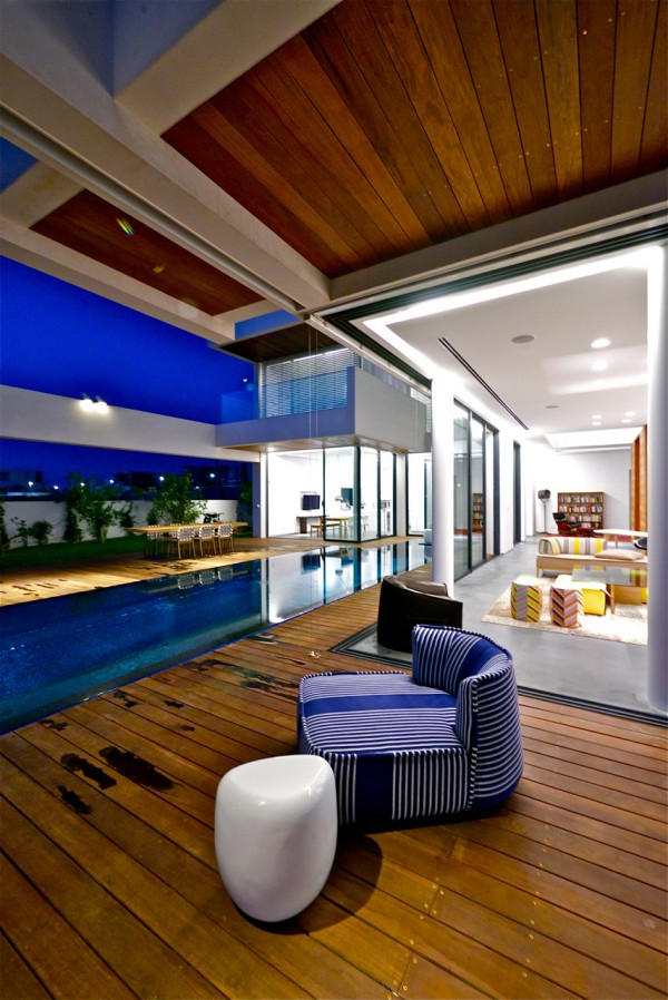
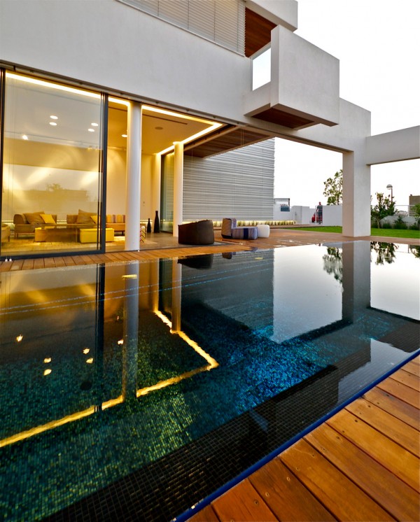
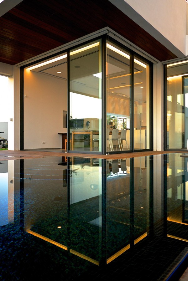
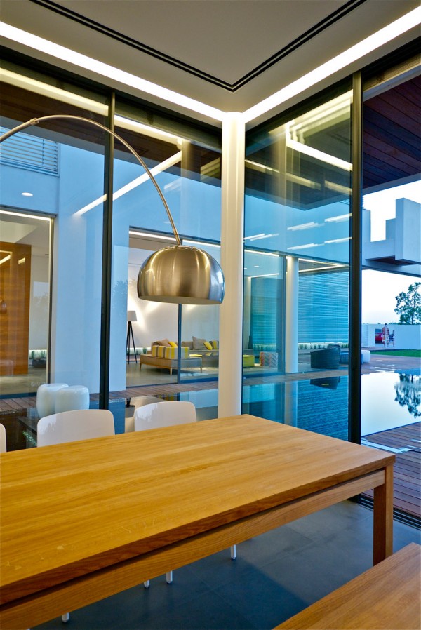
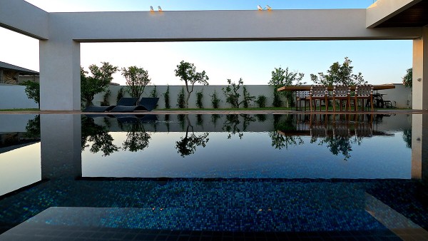
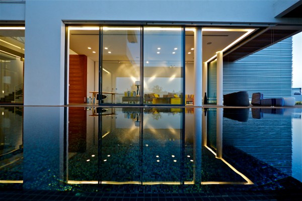
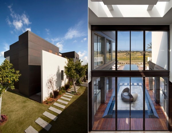
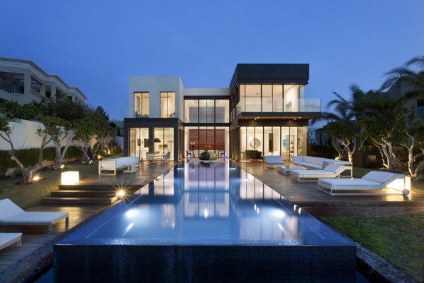
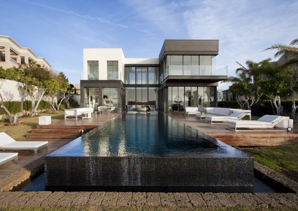
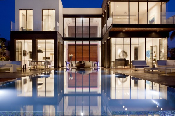
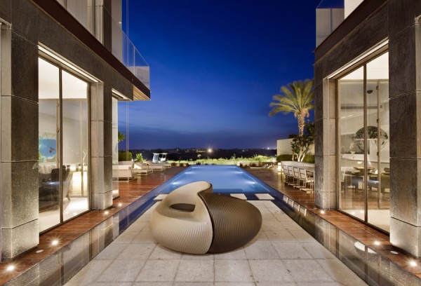
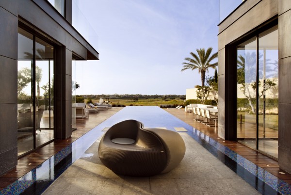
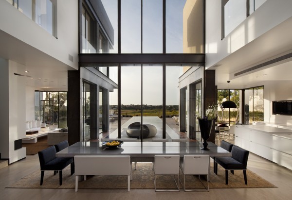
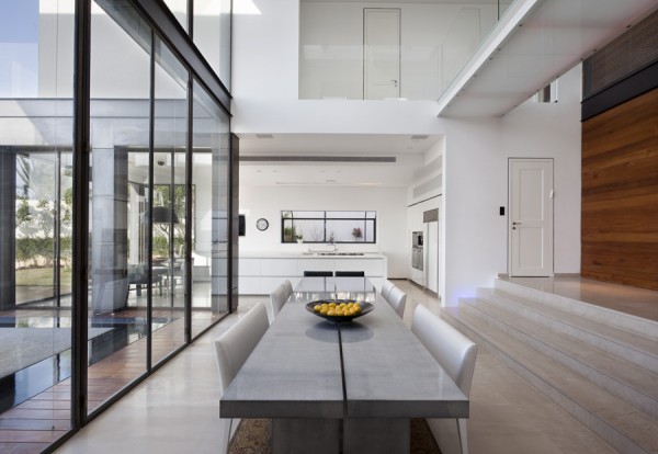
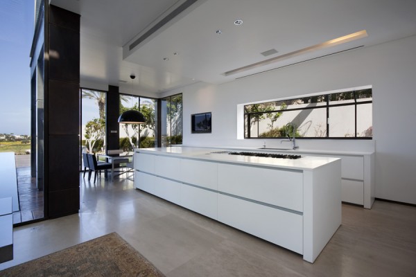
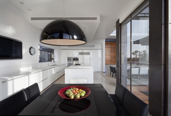
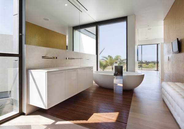
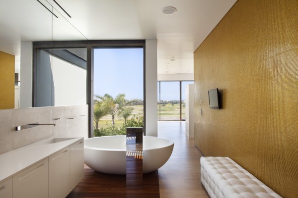
…design took into consideration the impact of the natural factors on the edifice, including wind directions, sun and natural light allowing the users to enjoy the sea breeze and natural ventilation. The interior and exterior spaces were designed as “a whole”. Minimal structure, transparent walls and long vistas to the yard and pool helped blur the borders between the inside and the outside. A multi-functional wall stretching from one side of the house to the other is seen as though it is floating. The wall is covered with aluminum profiles in various sections. These sections have an esthetic side creating breathtaking views as one is gazing to the entrance of the house. On top of that, the profiles are insulated and have a role in decreasing energy lost in the house. The materials used were basic and natural – teak wood, aluminum, glass and grey basalt floor finish.
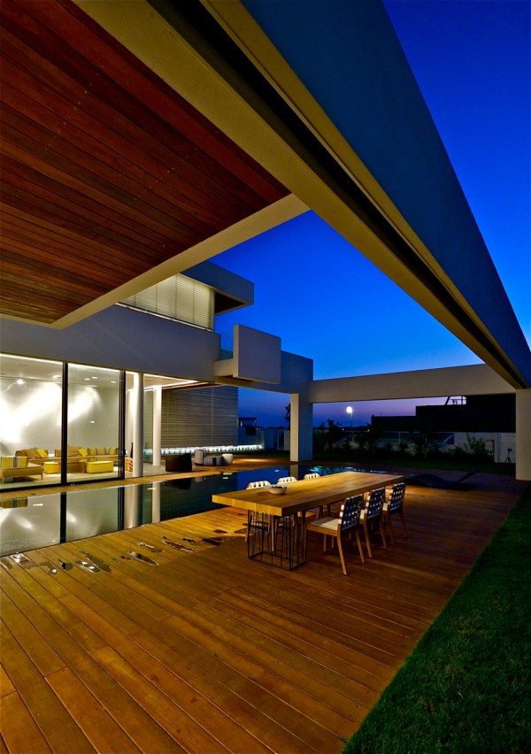
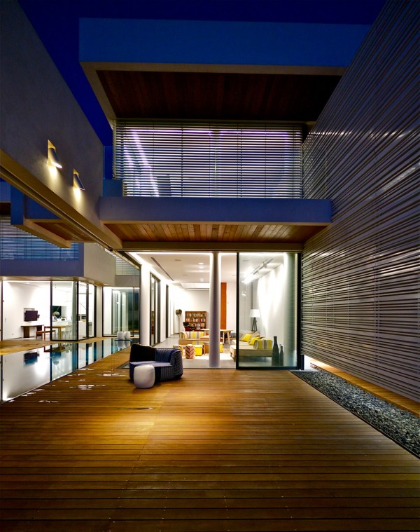
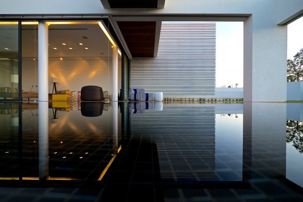
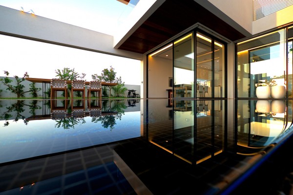
Share it on any of the social media channels below to give us your vote.
Your feedback helps us improve.

Welcome to our photo gallery of 32 modern home designs.
I remember viewing my first modern home that was built in the smallish town where I grew up. There is a mountain on the east side of town where large homes were built. It was the premiere neighborhood in our town because the views are incredible.
Far up the mountain in the late 80’s a family built a modern home that deviated from the usual West Coast style of homes that were popular on the mountain. The sparkling new white cube-style home with cliff-edge pool shone like a jewel on the mountain. I was smitten… and often went up the mountain to enjoy the views and the homes.
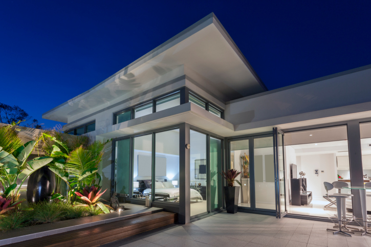
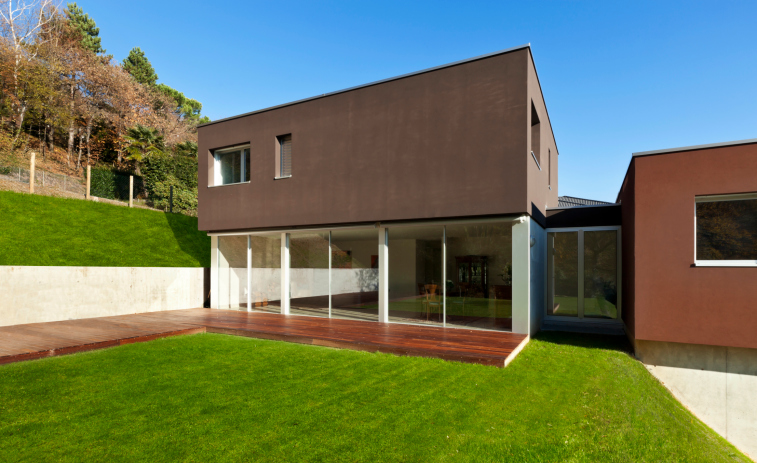
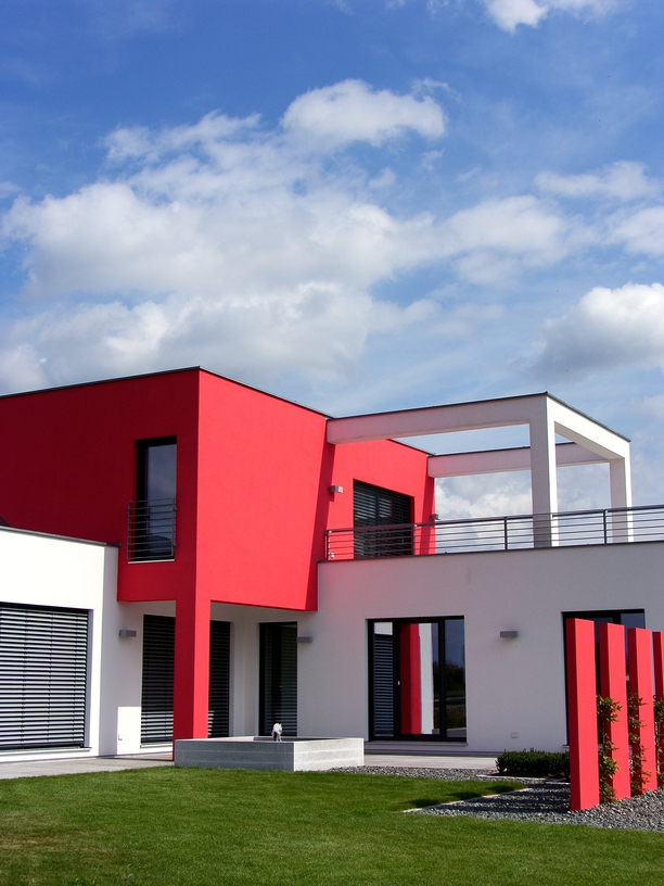
Our modern home designs gallery below features a range of modern homes with respect to design and architecture. Some of our featured homes are truly modern in the strict sense of the word while others are contemporary in design.


Click here to view another luxurious modern home!


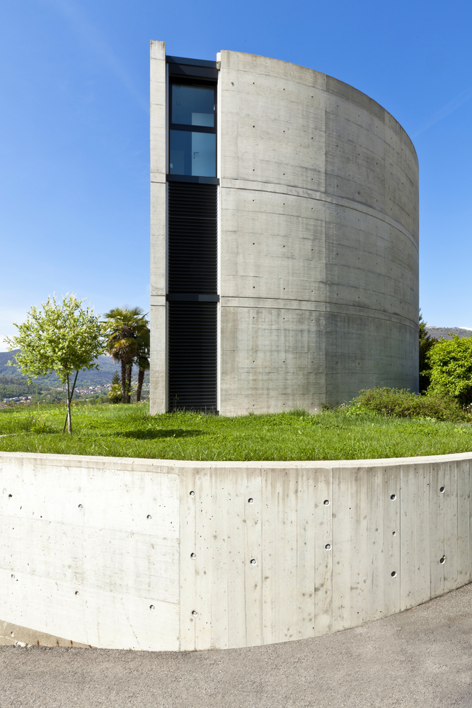

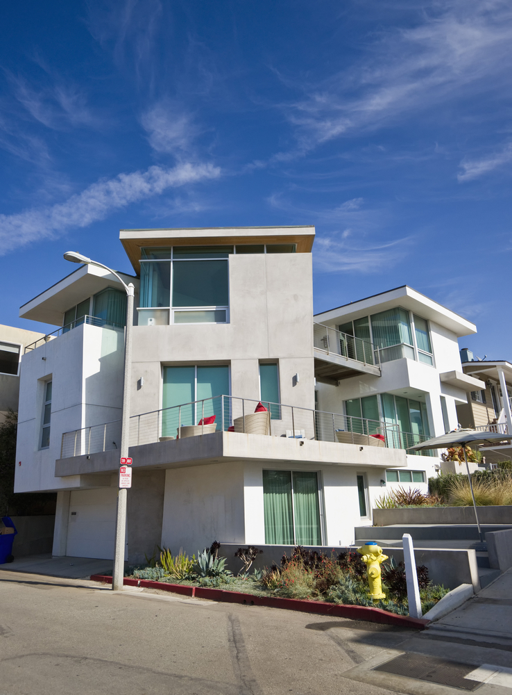
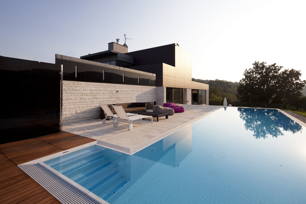



We love the gorgeous pool in the above shot….click here to see more fabulous backyard swimming pool designs and ideas!


Don’t miss our special gallery on wooden decks for more great ideas for your outdoor space!

See another gorgeous cliff-side project from one of our partners!
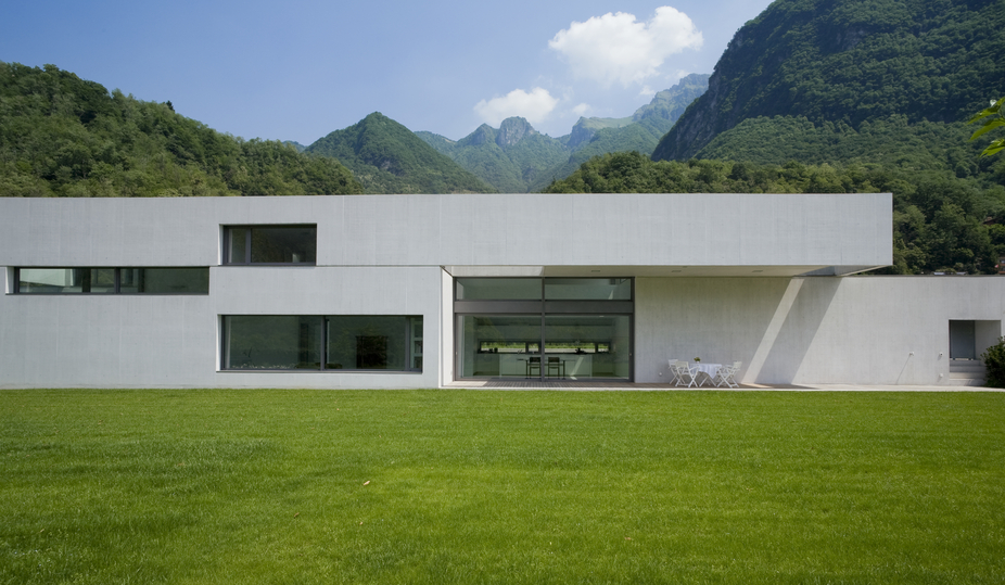


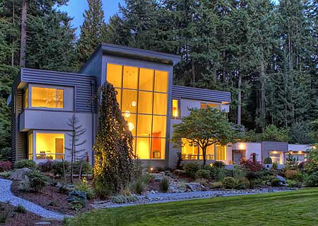 The above home is a good example of modern prairie style. The center of the home is the massive great room with the towering 2-story window
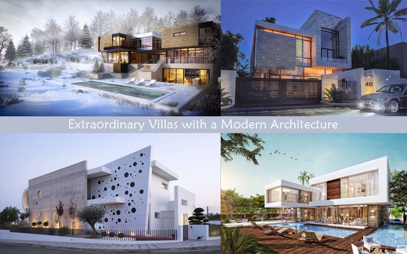
When it comes to architecture, judging a book by its cover can unlock a world of inspiration. These modern exteriors display a wide range of stylistic influences but they all have one thing in common: they embrace the constraints and challenges presented by their environments by creating a unified experience between landscape, materials, and form. These buildings don’t disrupt the landscape – they provide a new way to experience it. For today we gather A Set Of Extraordinary Villas with a Modern Architecture. Blurring the lines between vernacular architecture and modernist design principals allows home exteriors to become something more than just a beautiful facade.
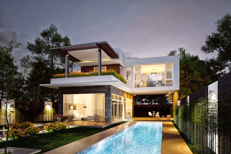
This home takes full advantage of its narrow plot. The pool runs alongside a tasteful garden and terminates at a patio sheltered by the room above. A tidy row of bamboo softens the look of the modern striped fence.
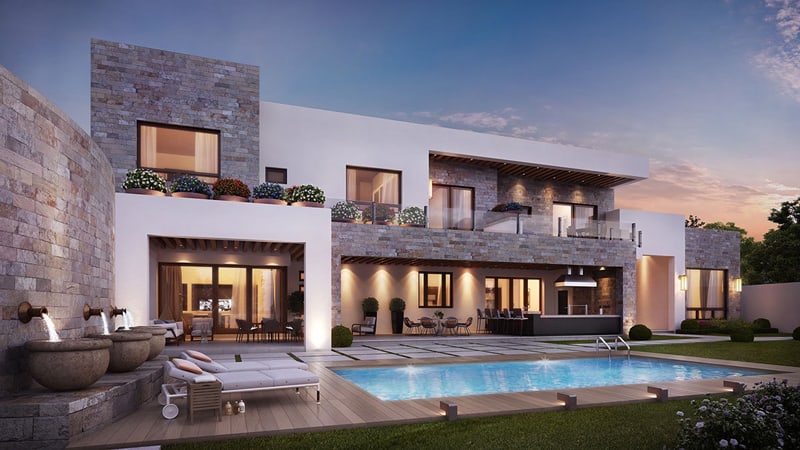
The juxtaposition between the smooth white walls and textural stone cladding exert amazing visual appeal. Don’t you just love the cistern/urn-style fountains integrated with the retaining wall? The shapes echo the planters used on the upper balcony and, taken together, provide a touch of classical appeal to an otherwise fully contemporary design. Project designed by Topsidefront.
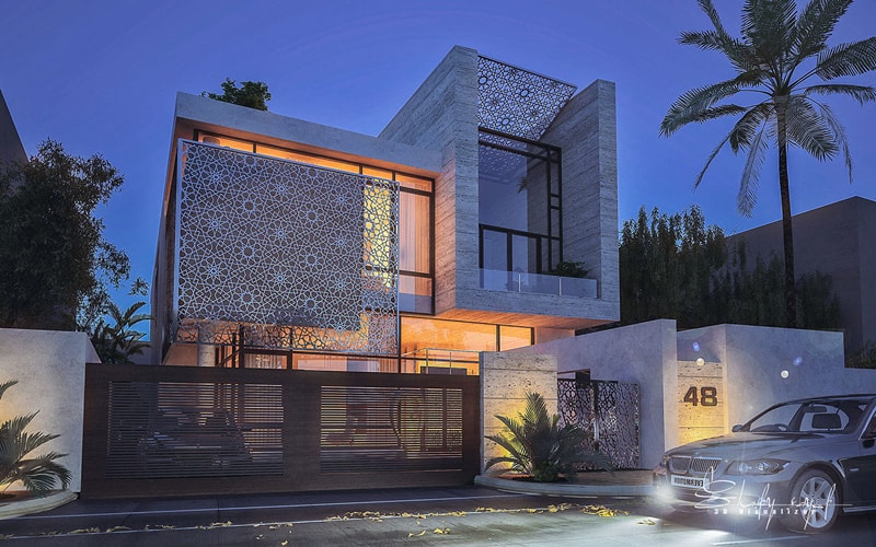
Intricate girih strapwork forms a metallic screen to shield the open volumes. A lower horizontally slatted wood screen offers a more discreet aesthetic that directs attention upward. Project designed by Shady Sayed & Nour El Deen Khaled.
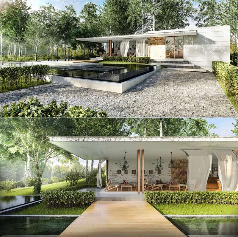
A modern boardwalk crosses a carefully framed channel of water, leading to an ever-so-slightly elevated indoor/outdoor living space decorated with trendy diamond frame lighting and streamlined furniture. Project designed by Thanh Nhan Tu.
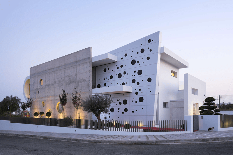
This perforated building (located in Nicosia, Cyprus) is a striking blend of angular construction and playful port windows. Not pictured – but alluded to on the left – a u-shaped fold gives the back of the home an open and organic aesthetic that smartly contradicts the sharp facade.
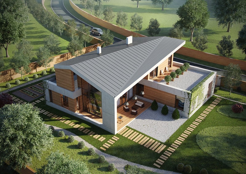
Orderly, linear, folded – rustic wood cladding and sleek concrete panels help this home feel like the perfect compromise between suburbia and country living by Yuriy Bochkaryov.
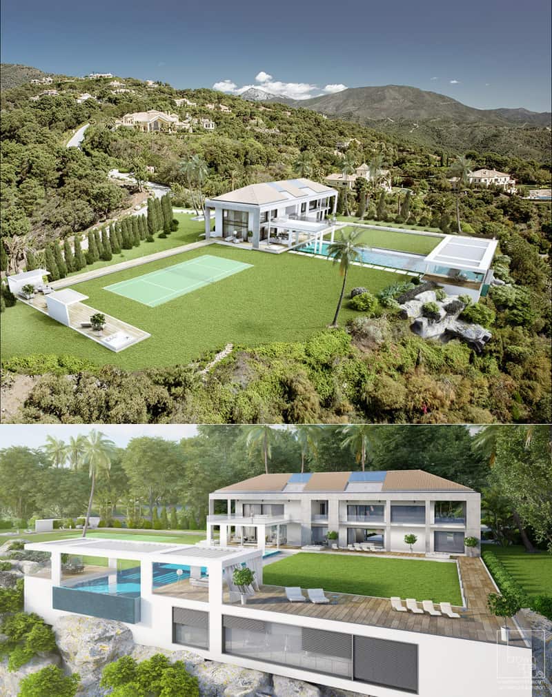
Built into the cliffside, this home features classic Greek influences mixed with notes of streamlined modernism. An observatory-type space sits discreetly underneath the patio by Brown And Blue.
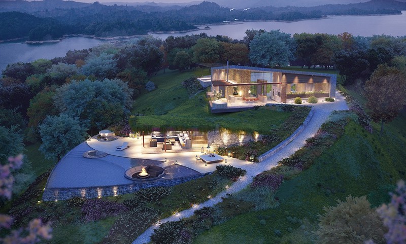
Visualized as a part of a resort for the “unplugged yet not-disconnected”, this space is carefully integrated into the surrounding landscape. It sits perched atop an overlook, its foundation plunges into the earth and emerges from the hillside as a chic entertainment space. The pool’s sunken fire pit is especially inspiring!

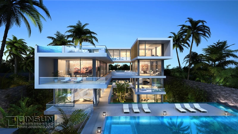
Part of a villa hotel project, this u-shaped retreat embraces its tropical environment. Small palms in the courtyard extend the landscape. Project designed by Xavier Xu.
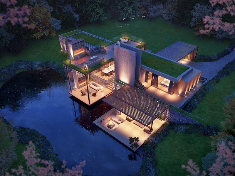
Here, there are no boundaries. A verdant stone wall intersects the main volumes, and the rooftop lawn surrounds an outdoor living space on the roof. The stairwell itself is the most substantial part of the glass-clad design by TRES 31.
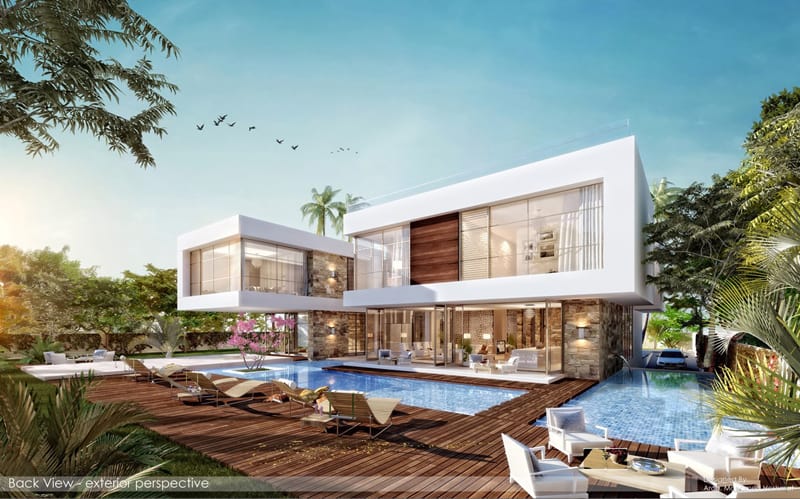
The home architecture seems weightless and divine, but the lovely pool deck deserves a second look as well. The furthest portion extends out from the underneath a breathtaking cantilever dining room, transitioning from smooth white to sumptuous dark wood that matches the singular section of timber cladding on the upper story of the home. A neat boardwalk provides another route of access to the entertainment areas. Project designed by Mohamed Heshmat.
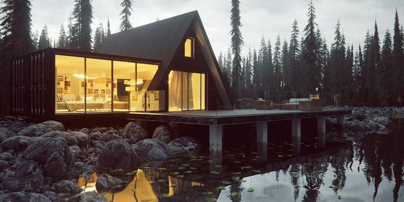
A sleek rectilinear volume intersects with a strong triangular prism. This unique form helps to enhance – rather than obscure – its connection with the conifer forest behind it. Project designed by Maxim Jurov.
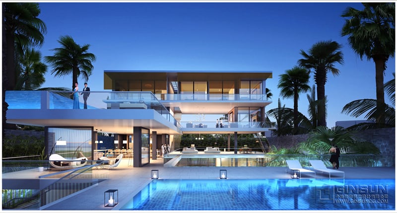
Pools occupy multiple levels. The topmost pool features clean glass walls to preserve the view for people lounging on the balcony, and to give swimmers an incredible way to experience the landscaped surroundings.
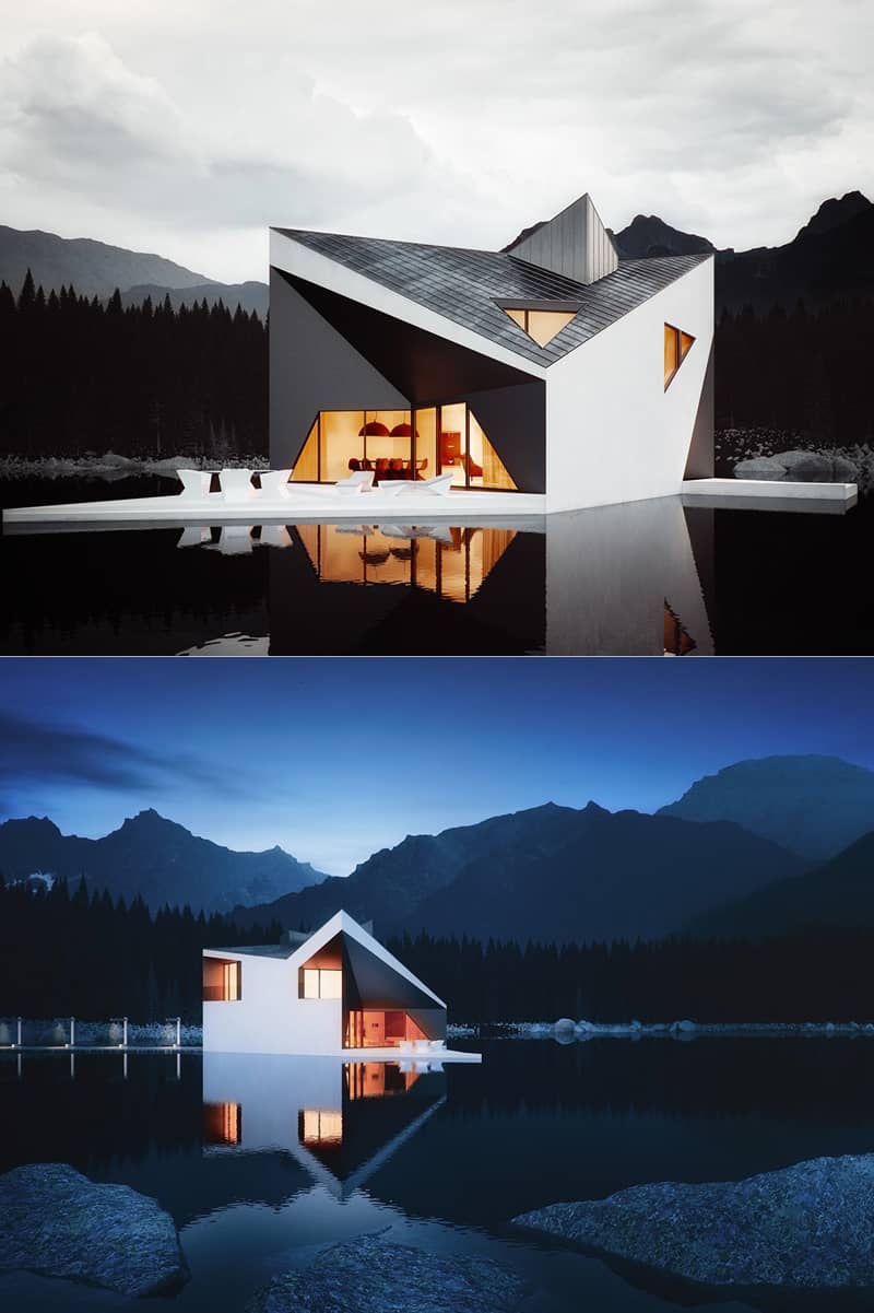
Rendered by Michal Nowak and designed by 81.WAW.PL architects, the Crown House projects its stoic form across a still dark lake. The somber color of the water is reflected in the treatment of the charcoal-colored eaves, heightening contrast and making the folded architecture look even more dramatic. Project designed by Michal Nowak.
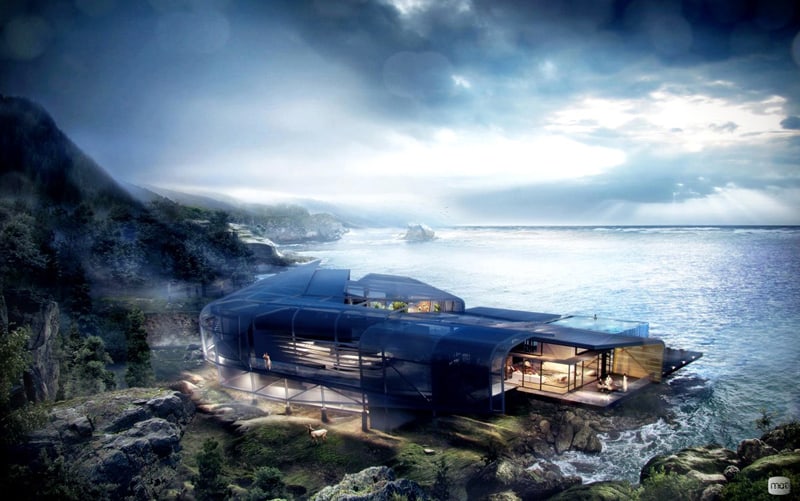
A gorgeous cliffside home, embraced by a curved glass shel by Walter De Marco
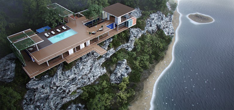
Another gorgeous cliffside concept, with a gravity-defying observation deck. Recreation areas occupy the top floor, with private areas enjoying the shade beneath. The uppermost room would make for an especially inspiring office. Project designed by Yuriy Bochkaryov.
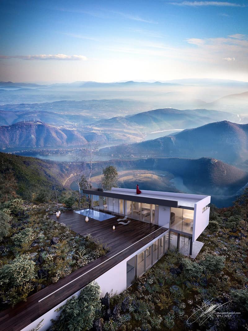
Roughage and timber resolve into orderly rectilinear architecture. The visualized landscape is whimsical, but the home itself is equally breathtaking by Tung Le Xuan
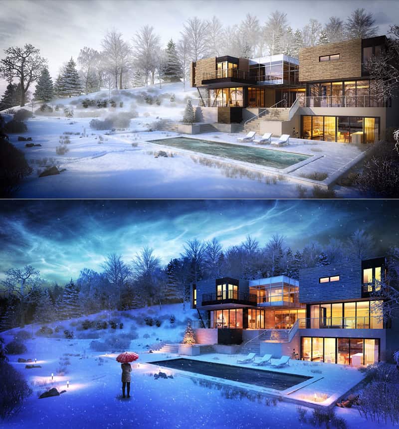
Wintertime visualizations are surprisingly rare but this home looks like the perfect place to warm up as the snow falls outside, especially with the yellow-hued lighting that emanates from the interior. Porject designed by Alex Barcelos.

1. Open Max, and under the Create tab change the Standard Primitives drop down to Extended Primitives, and then create a Chamfer Cylinder in the centre of the Perspective view. Remember that most of the Extended Primitives have 3 creation parameters that must be created: Radius, Height and Fillet. Here is what it should look with all three parameters created (Fig.01).

This is the only object we will create. Everything else we do from here on out will be copies of this object. We are also not going to convert it to an Editable Poly because, while it will give us control over the object at the sub-object level, we will lose the power to adjust and manipulate the Chamfer Cylinder primitive. This is important and much overlooked.Â
Just
so we are all on the same page, select this cylinder, go to the Modify tab and make the following settings, shown in Fig.02.

2. Alright, now using the Move tool, hold down Shift with the LMB (left mouse button) and move the cylinder up on the Z axis a little, then release the mouse. In the window that opens ensure that Copy is the selected method and hit OK (Fig.03).

Note: from this point on, I am not going to describe in detail how to make these copies, I will assume that you now understand how to do it!
3. Now let’s adjust this new cylinder’s primitive properties, so go to the Modify tab, make these changes and then move the cylinder dow, like so (Fig.04).


5. Copy it, switch to the Front View and then move it down and make these adjustments (Fig.06).


It’s becoming the norm for cinema tickets to come with a pair of polarized glasses, and increasingly, special versions of films are being made in IMAX 3D too. As this list shows, though, 3D movies still seem to be limited to two genres: action blockbusters and children’s animations. Will 2016 be the year when period drama, European cinema and the indie scene discover the opportunities of stereo 3D, we wonder?
In the meantime, check out our list of this year’s biggest 3D movies and let us know in the comments whether you plan to see them in 2D, 3D or IMAX 3D…
With 2012’s The Avengers making over $1.5 billion worldwide and becoming the third-highest-grossing film in history, a sequel was inevitable, and Avengers: Age of Ultron is one of the most eagerly awaited 3D movies of 2015.
The film will have an astonishing 3,000 visual effects shots, provided by seven to 12 visual effects companies. Obviously this includes Lucasfilm’s Industrial Light & Magic, which opened a facility in London last year to work on the film, which will be released in both 3D and IMAX 3D.
Intriguingly, ILM has developed a new motion capture system for use on Age of Ultron called Muse, which can better capture the actor’s performance and combine different takes. Can’t wait to see what that looks like…
A remake of the 1982 horror classic, Poltergeist 2015 will be directed by Gil Kenan, written by David Lindsay-Abaire and produced by Sam Raimi. While we’re generally against pointless remakes of relatively recent films, Sam Rockwell is always a good turn, and we have to admit that the trailer looks pretty darn cool. Plus at least the addition of stereoscopic 3D brings something new to the table.
Will any of the Terminator sequels ever match up to the superlative Terminator 2, the 1991 sci-fi epic with early CGI effects that still put many modern movies to shame?
This, the fifth in the installment, will “reset” the plot and start off a whole new trilogy. Now free from governership duties, Arnie is back in the titular role, with Alan Taylor directing and Legacy Effects responsible for bringing the Terminator endoskeletons back on to the big screen. The trailer looks promising, and the use of Imax 3D should provide a suitably epic experience to the viewer.
But we have to be honest here: it was this very unofficial teaser video, featuring a spoon and a tea cup, that really piqued our interest…
More post-apocalyptic unpleasantness comes with the first film in the Mad Max franchise in three decades. Tom Hardy, who played Bane in the last Batman film, takes over from Mel Gibson in the eponymous role, alongside a bald-headed Charlize Theron. The film’s been in developmental hell for over 25 years, with constant start and stops, so here’s hoping it was worth the wait.
But here’s what’s really exciting us. Rather than being retrofitted with stereo 3D as so many modern films are, Mad Max 4 will be shot using 3D rigs and cameras that are being specially developed by director George Miller, according to Inside Film. And that might, just might, be a total gamechanger.
Yes, the franchise that changed everything is finally back for 2015. Now under the Disney umbrella, a seventh installment in the series will be released this Christmas featuring stars of the 1977 original.
Set 30 years after Return of the Jedi, the film will be released in 2D, 3D and IMAX 3D. Director JJ Abrams has pleased fans with his decision to shoot on film rather than digital, and make greater use of practical effects and rely less on CG than the prequels did. Once again, John Williams will provide the music and ILM the effects.
This may be stating the obvious, but… We. Just. Can’t. Wait.
Twenty-two years after the events of 1993’s Jurassic Park (anyone spot a theme developing in this list?), the dinosaur tourist attraction is finally up and running. But then visitor rates start to decline, so a new attraction is created to re-spark public interest: a genetically modified hybrid dinosaur called Indominus Rex. Not terribly surprisingly, things do not go exactly according to plan…
Colin Trevorrow is directing a screenplay he co-wrote with Derek Connolly, while visual effects supervisor Phil Tippett and Industrial Light and Magic also return to take charge of pixels. With the original movie being such a landmark in CGI moviemaking, it’ll be fascinating to see how much the tech of dinosaur-making has advanced in the intervening years.
While the Steve Carrell-voiced Gru may have been the official star of Despicable Me and Despicable Me 2, it was his small, yellow and somewhat incomprehensible lackeys that kids were queuing round the block to see.
Suitably enough, 2015 sees the lovable Minions get their own feature length adventure, with a voice cast including Sandra Bullock, Michael Keaton, Allison Janney and Steve Coogan. Produced by Illumination Entertainment for Universal Pictures, this promises to be one the summer’s biggest kids movies, and all in glorious stereoscopic 3D.

Diffcult to believe we know: but already it’s the end of an era, as the final part of the final Hunger Games book plays out on the big screen. All the regular cast return, including the late Philip Seymour Hoffman who’ll appear in fewer scenes than planned now director Francis Lawrence has decided not to use CGI to fill in the blanks.
The only Hunger Games film to get the 3D treatment, this one will be released in 2D, Digital 3D, RealD 3D and IMAX 3D. And with Panem’s revolution against the Capitol turning into full-scale, explosive war, this is one we’d recommend seeing on as big a screen as possible.
Yes, this one made us do a double-take as well. It’s only been 10 years since the first Fantastic Four film, but apparently Marvel thinks it’s time for another reboot of the franchise already. So here comes an all-new retelling of the story, directed by Josh Trank and starring Miles Teller, Kate Mara, Michael B. Jordan, Jamie Bell, and Toby Kebbell.
Interestingly, Trank has said that the look of the film is heavily influenced by David Cronenberg movies such as 1981’s Scanners and 1986’s The Fly. OTOY,MPC and Weta are handling the visual effects, and a sequel is already in the pipes for 2017.

Disney does ‘alternative history’ in this new 3D kids animation, which asks “What if the cataclysmic asteroid that forever changed life on Earth actually missed the planet completely and giant dinosaurs never became extinct?”
The tale follows Arlo, a 70-foot-tall Apatosaurus with a big heart, who teams up with —a young human boy named Spot. Directed by Peter Sohn, the 3D animation will be produced by Pixar Animation Studios and released by Walt Disney Pictures.


 Select the source object, and then on the Object Type rollout, click Scatter.


