Lets Chat
We would love to hear from you and see how we can help 🙂
-
Call Us On
-
Come Find Us At
#150 D Park View -Gulan St.-Erbil-Iraq
-
Email Us At


Nothing new under the sun. Here we come again with a bushy one.
Today, you will need the ARRAY command, the FILLET command and the OFFSET command (we made an extensive use of the OFFSET command in DAY 7). There is no need to mention that you will need the LINE command, the CIRCLE command, may be the ROTATE command too.
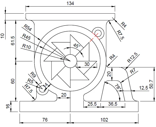
The following image provides some additional information needed to perform the exercise with success.
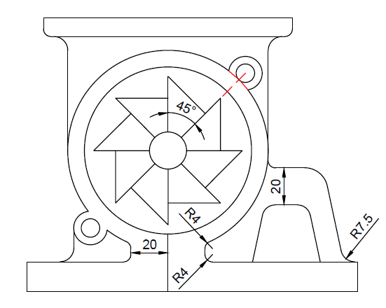
For the sake of exercising with the HATCH command, you can HATCH the above project at the end if you wish.

There is not much hardship in the session we are about to have. This should be a piece of cake if you have been following the series since DAY 1.
Just for the sake of knowing, here are couple of things you need to know before diving into today’s exercise:
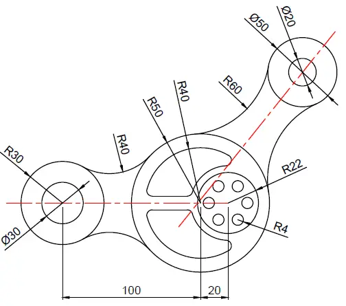
To avoid the preceding image to be too bushy, we’ve split information. You can find the remaining part of the information you need in the following picture.
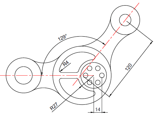

In this post, we are going to be perfecting how to handle positioning in AutoCAD.
The Object SNAP mode will be important for this session, The exercise itself is an easy one, but you need to be a bit cautious about where each of the object is placed in the project.
The use of the OFFSET command will be helpful and the ability to create a circle with the feature Tan, Tan, Radius.
The following is the exercise we are going to be using in this session.
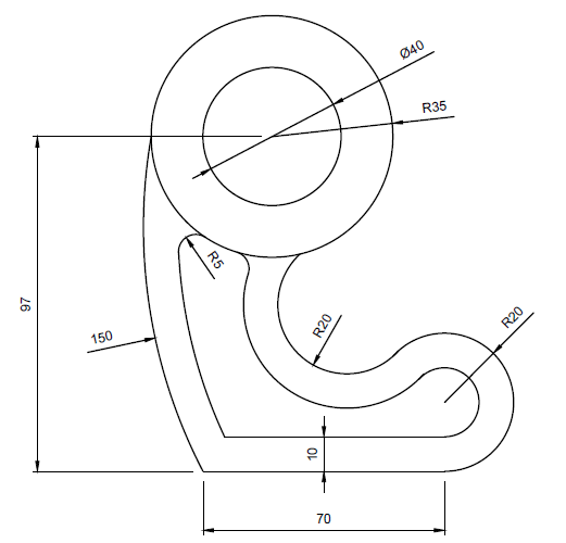
Additional important information are brought using the following image.

The following is the key image which will help complete this project.
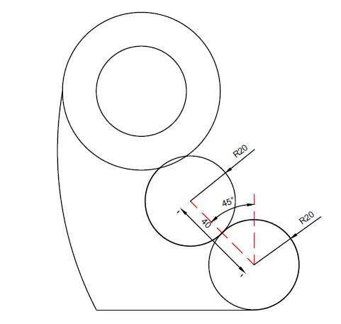
You need to first get the above image then Trim it, and you should get the following.
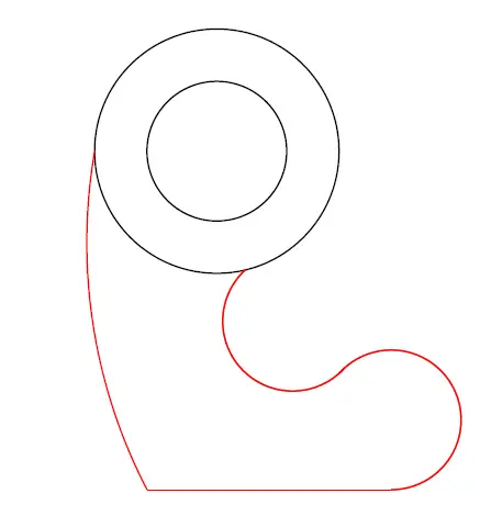
What you need to do now is: Give the red part an OFFSET of 10 units, and you will end up with the following.
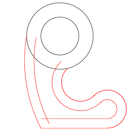
It is all clear now, you surely know what to do next to complete today’s task. Do not forget the two FILLET of R5 we have just below the two circles.
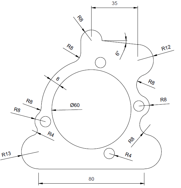
In this session there will be nothing difficult, except the fact that it will help you develop yoursense of analysis while using AutoCAD.
Looking at the exercise below, you should be able to, from a first look, determine all commands you need to be able to accurately replicate the object of today’s experiment.
You by now possess all you need to be able to complete the following without any problem
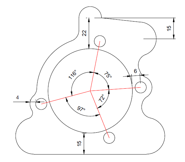
For some, figures above will not be self-explanatory enough, that is why we are bringing the following image. Pay attention to the skeleton-image used while creating the project, you will notice this is even easier that what it seemed at first.

Our suggestion will be to start from the base line (line of 80 units). All information are provided for this not to be a headache.
Feel free to drop a couple of words below in case of difficulties.

All here is a déjà-vu. Last session, we’ve learned how to use the ELLIPSE command in AutoCAD, in this session we are coming back with an even easier ellipse.
BUT, but now, the focus will be made on something totally different.
in Learn-AutoCAD-DAY-6, we have worked with the ARRAY command for the first time. Today you will need that command line more than EVER. And it is compulsory to have mastered it before trying the coming exercise.
NOTE: Element in the array are equally spaced around the ellipse.
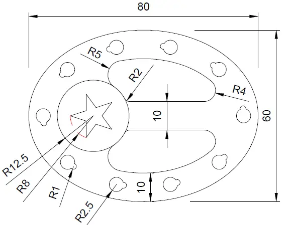
On the following image, the red line represent the PATH of the array. It resulted of an OFFSET of 5 units from the outer ellipse.
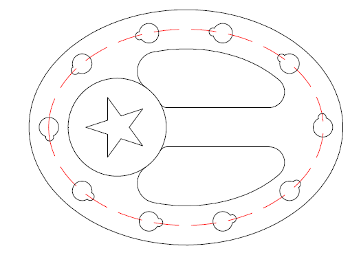
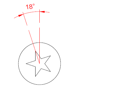
The object in the array is nothing but the following
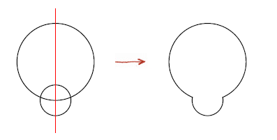
You can find dimension of the circles on the first image above.
The only thing that might be hard to accomplish here is the array. There is nothing like ARRAYELLIPSE in AutoCAD, what you need to do to create this array is using the ARRAYPATH.
To use the ARRAYPATH command using an ELLIPSE, you need to cut the ellipse into two, and use the ARRAYPATH on each of the side, that is it.
We would like to let you fight with it and figure it out yourself, using information we provided above.
Feel free to drop your opinion and concern in the comment section below.

Here is an exiting one! We have just noticed we needed to add more ingredient to our experiment today, for some reasons.
Last DAY, we noticed the exercise we were working on made it too easy to escape the MIRROR command, today, we are coming with one which is meant to make it almost impossible to accomplish without making use of the MIRROR command.
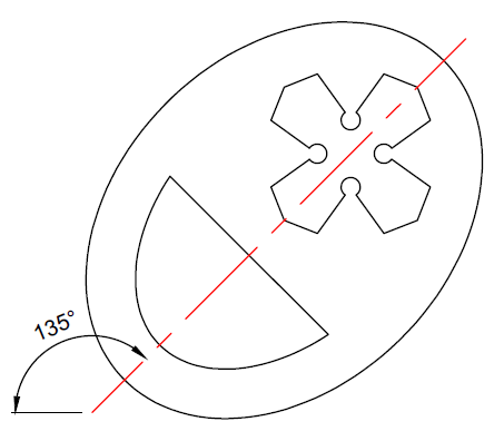
The two red lines are both axis of symmetry of the object.
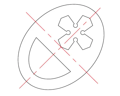
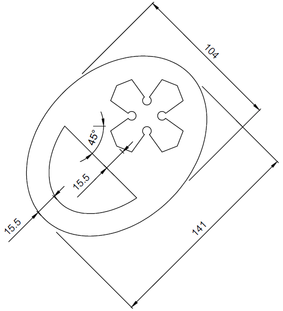
Details about the object inside the ellipse.
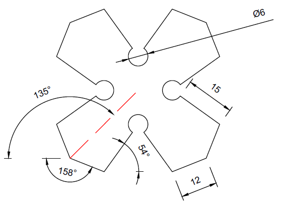
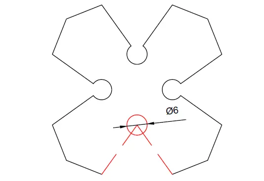
We will need to use the ELLIPSE command in this session.
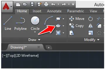
To use the ELLIPSE command
For this experiment, we will make use of the POLAR TRACKING. Activating the following mode of the POLAR TRACKING will contribute to ease our task.
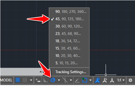
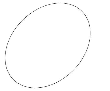
The ellipse is bent with an angle of 45 degrees.
You should have the following.
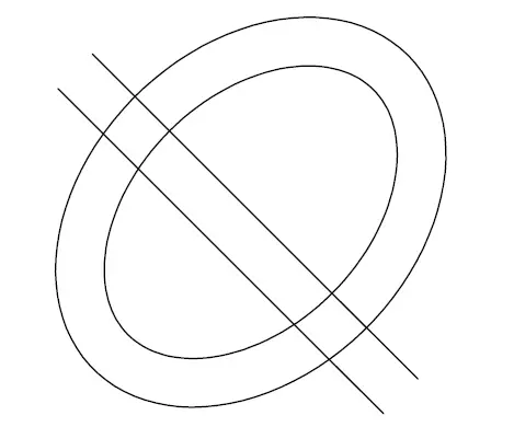
After creating the ellipse all you need to do is find the center line of the ellipse, OFFSET the ellipse and the line with an OFFSET value of 15.5. The resulting image should look similar to the following.
Use the TRIM command to obtain the wanted object.
To create the cross, you need to:
Create the following, you can find the length of the red line using information given earlier.
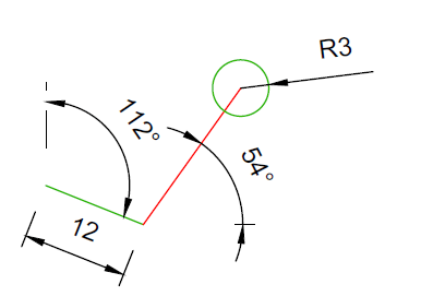
Create a mirrored copy of the current object, the line of symmetry should be a line with and inclination angle of 45 degrees starting from the left end of the drawing.
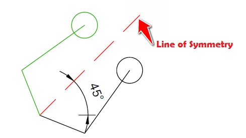
Create a vertical line that will serve as the new line of symmetry. The new line must have an end common with the center of the newly create circle.
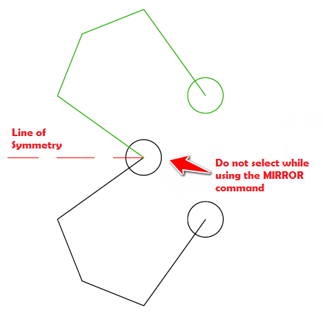
You don’t have to select the highlighted circle while you use the MIRROR command.
After obtaining the figure we have just obtained, you can use the same trick to get the other part of the image. And that will be it. Combining both structures should not be an issue.

One of the command we have not been using since the beginning of this series is the MIRROR command. We expect to force its use with today’s session.
Today’s rule will be a bit altered in the sense that we wish you use the MIRROR command. How? If you look closely at the image below you will notice that the object is a sort of symmetric. Imagine a vertical line cutting it into two, both sides will be just identical mirrored copies.
Here is the object of today’s experiment.
We’ve said earlier that the object is symmetric, let’s see what a part of it would look like. (The line in red seeing as the line of symmetry)
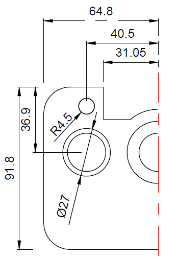
After removing all FILLET, here is what the image looks like

Here are some information that might be helpful
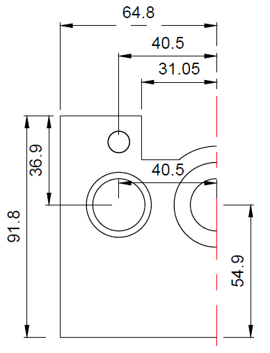
You can just do the inverse operation to mount that object walking from the last image right above this to the first image we had in the beginning of this session.

In this session we will be challenging ourselves to learn how to play with the ARRAY command in AutoCAD.
The image below is one of those that may best serve this purpose. It is to be noted that all slots are equally spaced around the circles.
Feel free to visit the post where we practiced and talked about the use of the ARRAY command in AutoCAD.
There is not much to be done in this one but the proper use of the ARRAY command. All you will need is to have mastered the TRIM command, the LINE command, the FILLET command and theCIRCLE command.
Below we have split annotations in different figures to avoid having a bushy image. Combine all information available on the figures if you want to accurately replicate today’s exercise.
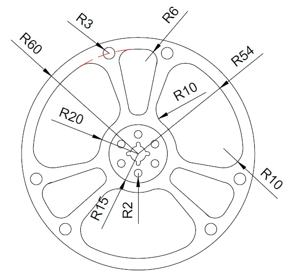
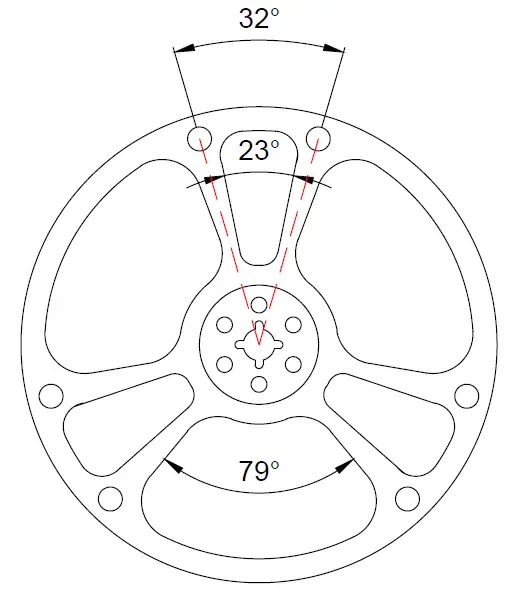
Piece in the center of the exercise.
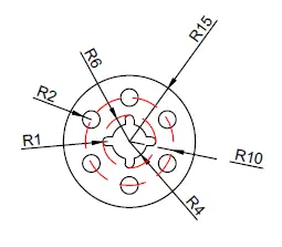
The following image might be helpful to you to have a good start
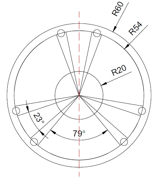
After proper TRIMMING, you will be left with the following
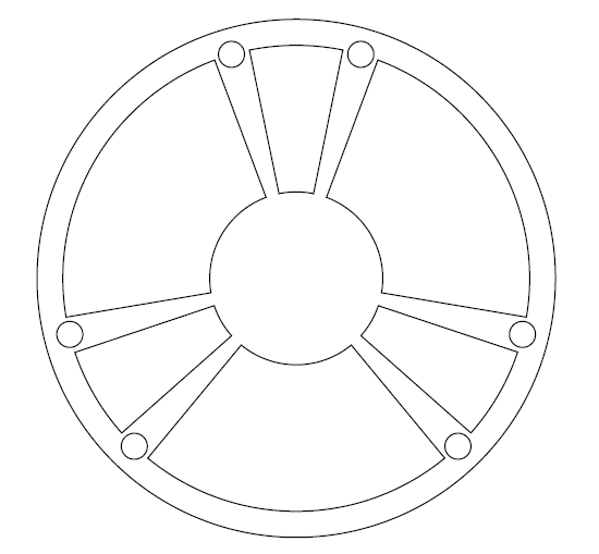
Now all you need to do is to use the FILLET command to round edges and create objects that are in the center of the figure.
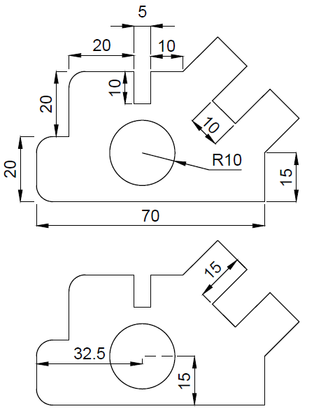
The following should have nothing new to you if you have been here since the beginning. In this session, we are going to make good use of what we have learned so far.
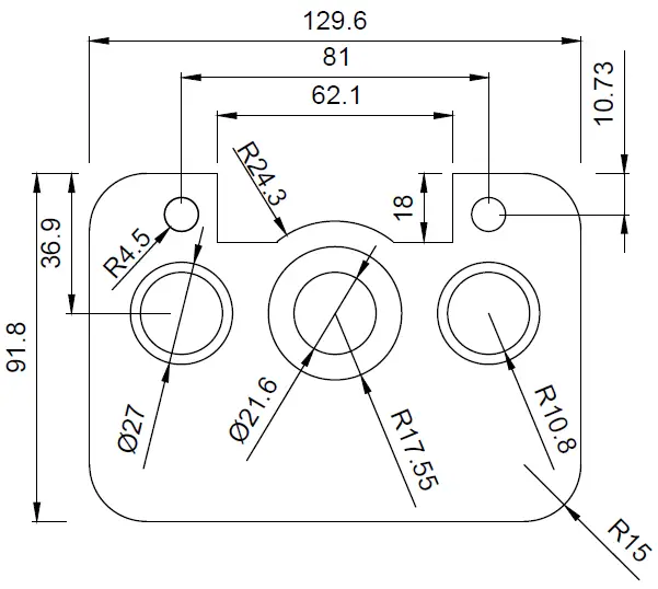
The image below will serve as today task.
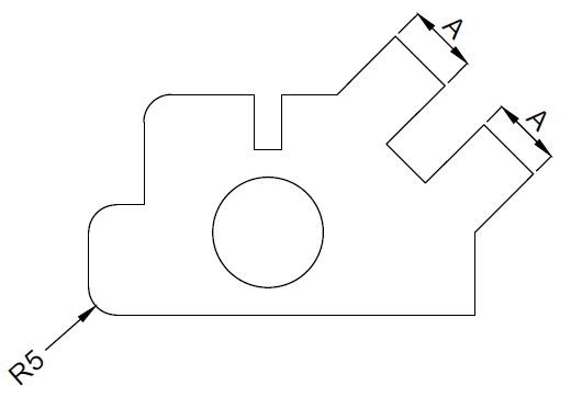
All Fillet in the following exercise are 5 units. (Learn more about the FILLET command in AutoCAD)
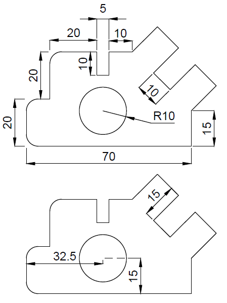
You do not need to know the dimension of A to be able to accurately replicate the exercise. But it is crucial to know that the value of those lines are the same, that is the reason we called it A.
As I said earlier, all FILLET are R=5. We have 3 FILLET in the following exercise.
You will need to use the UCS command to place the circle at its appropriate distance using the same technique we used in the last session.
The following information will also be important to know.
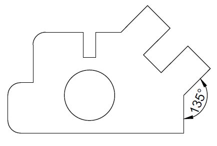
Basically, there is nothing added than the FILLET command here. Ignore the FILLET, complete the figure and you can get those FILLET done at the end of the task.
Feel free to drop your thoughts below in case of any question or pinion.