Graphic World

Categories
Articles Learning

Introduction To Auto desk AutoCAD | DAY 20

Learn AutoCAD basics: DAY 20

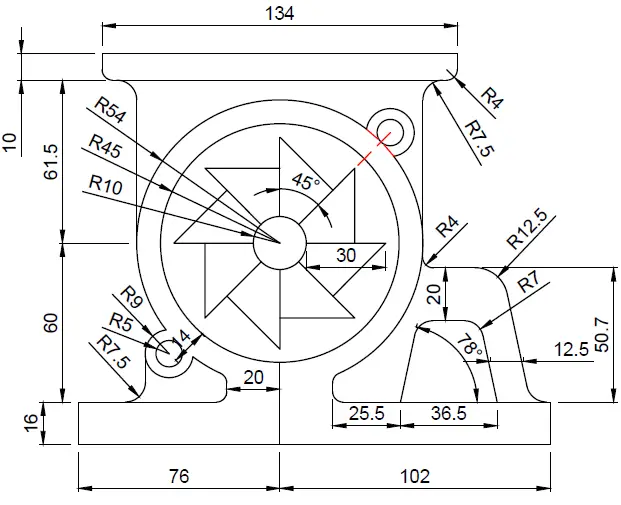
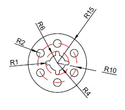
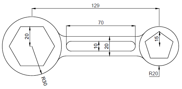
Nothing new under the sun. Here we come again with a bushy one.

Today, you will need the ARRAY command, the FILLET command and the OFFSET command (we made an extensive use of the OFFSET command in DAY 7). There is no need to mention that you will need the LINE command, the CIRCLE command, may be the ROTATE command too.

LEARN AUTOCAD BASICS

FIGURE 1

learn-AutoCAD-Bacis

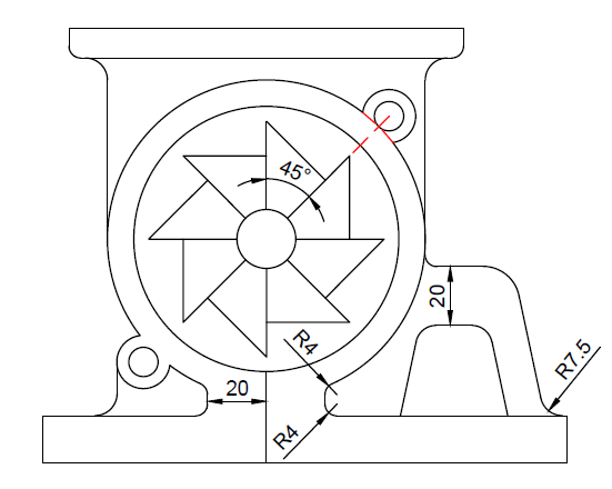
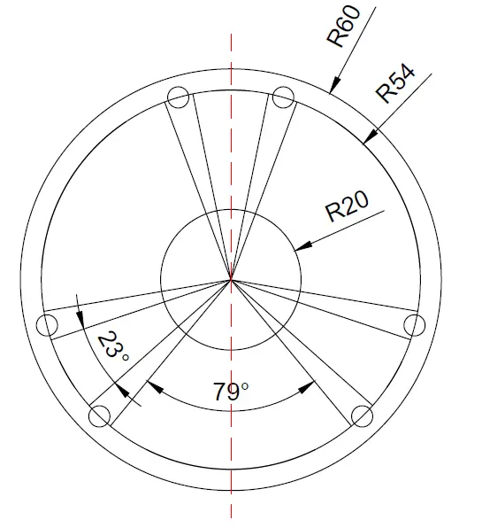
FIGURE 2

The following image provides some additional information needed to perform the exercise with success.

learn-AutoCAD-Bacis

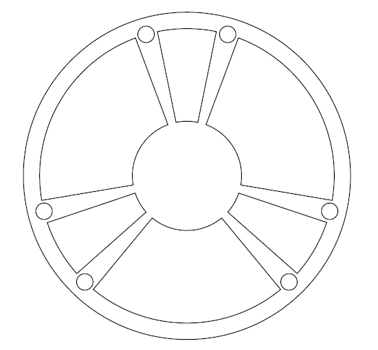
For the sake of exercising with the HATCH command, you can HATCH the above project at the end if you wish.

Categories
Articles Learning

Introduction To Auto desk AutoCAD | DAY 6

Learn AutoCAD basics: DAY 6

In this session we will be challenging ourselves to learn how to play with the ARRAY command in AutoCAD.

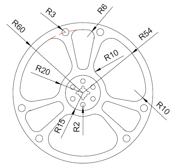
The image below is one of those that may best serve this purpose. It is to be noted that all slots are equally spaced around the circles.

Feel free to visit the post where we practiced and talked about the use of the ARRAY command in AutoCAD.

LEARNING AUTOCAD BASICS

There is not much to be done in this one but the proper use of the ARRAY command. All you will need is to have mastered the TRIM command, the LINE command, the FILLET command and theCIRCLE command.

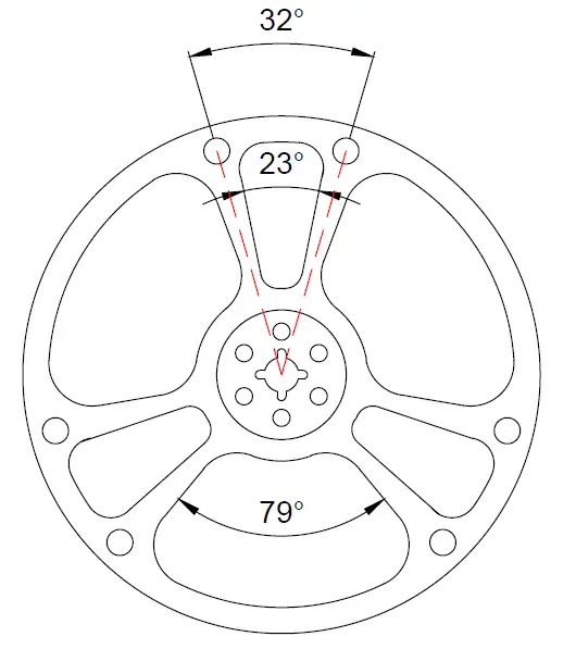
Below we have split annotations in different figures to avoid having a bushy image. Combine all information available on the figures if you want to accurately replicate today’s exercise.

FIGURE 1

learn-AutoCAD

FIGURE 2

learn-AutoCAD

FIGURE 3

Piece in the center of the exercise.

learn-AutoCAD

EXECUTION

The following image might be helpful to you to have a good start

learn-AutoCAD

After proper TRIMMING, you will be left with the following

learn-AutoCAD

Now all you need to do is to use the FILLET command to round edges and create objects that are in the center of the figure.

Categories
Articles Learning

Introduction To Auto desk AutoCAD | DAY 5

Learn AutoCAD basics: DAY 5

Hope we have providing some insights to you with this series of learning AutoCAD through exercises.

We previously worked on exercises that helped us master the following:

  • The use of the LINE command in AutoCAD
  • The use of the CIRCLE command in AutoCAD
  • The use of the TRIM command in AutoCAD
  • The USE of the UCS command in AutoCAD
  • and more


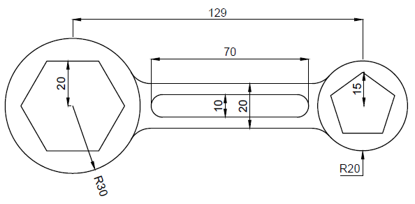
Today, we are going to continue learning and the object that will allow us do that is shown below.

learn-AutoCAD

As you can see the only added tools here is the POLYGON command which you will have to learn if you want to successfully replicate the image above.

LEARNING AUTOCAD BASICS

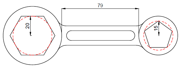
It is important to have you see the following.

learn-AutoCAD

It is important to understand that the two polygons do not have same characteristics. The Polygon on the left side of the image is a 6 side polygon circumscribed about a circle of R=20 and the Polygon on the right is a 5 side polygon inscribed in a circle of R=15. (illustrated on the image using the dashed red circle)

All fillet are R=10 units and remember that you need to learn how to create a polygon in AutoCAD before attempting to do this exercise.

A TRICK YOU CAN USE

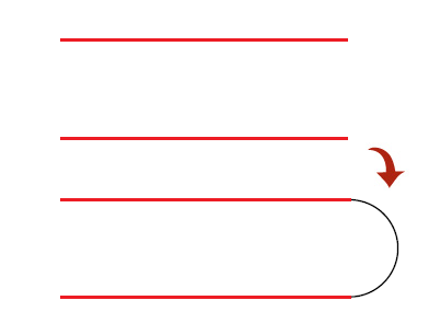
It is possible to use the FILLET command on two parallel lines.

learn-AutoCAD

Using all we have learned in previous sessions you should be able to come out of this one without any hassle.

Categories
Articles Learning

Introduction To Auto desk AutoCAD | DAY 3


Learn AutoCAD basics: DAY 3

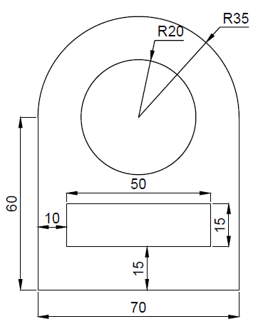
In this post we will be learning how to use the TRIM, CIRCLE command while trying to replicate the image below.

We have, in the last session, learned how to play with the LINE command and use Options of the Status bar. We will keep on playing with those features, adding up to them few others.

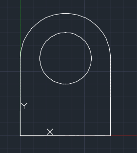
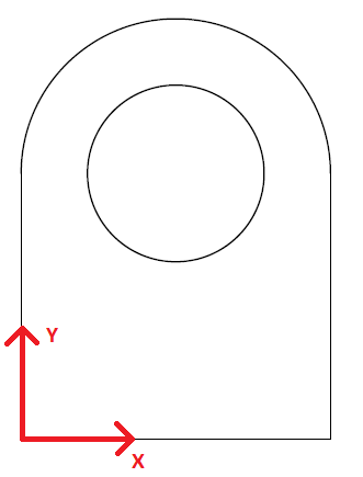
learn-AutoCAD

LEARNING AUTOCAD BASICS

The primary figure that will help easily replicate this exercise is the following.

learn-AutoCAD

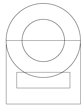
Two circles and two Rectangles.

What is the easiest way to get to this.

  1. Create the big rectangle using the LINE command
  2. Use the Center of the top side of the triangle to create the two circles.

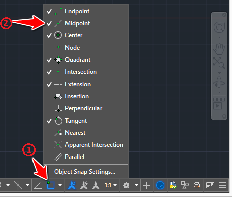
For step 2, you need to turn the Midpoint ON if you want to be able to find the center of that segment while creating the circle

Here is how to do it (right click on 1 and tick 2)

learn-AutoCAD

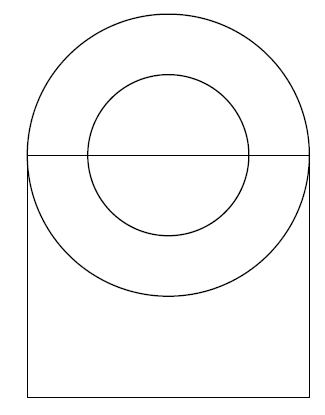
Now you should be at the following point

learn-AutoCAD

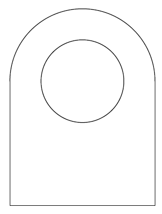
Trim the big circle and Erase the top side of the rectangle

learn-AutoCAD

Now all we need to do is create the small Rectangle. Given dimensions given above, if we consider that the left corner of the figure is at the point of coordinates (0,0), we need to start the small rectangle at the point of coordinates (10,15)

What we will do.

  1. Move the UCS to the left down corner of the figure
  2. Start the line at the point (10,15)

HOW TO MOVE THE UCS TO THE LEFT DOWN CORNER OF THE FIGURE

  1. Type UCS
  2. Select the point
  3. Move the cursor on the x direction and click
  4. Move the cursor on the y direction and click

This is what you are supposed to get

learn-AutoCAD

Notice the UCS

learn-AutoCAD

Now you can easily start the line at the point (10,15) and create the small rectangle.

EXERCISE

learn-AutoCAD

Categories
Articles Learning

Introduction To Auto desk AutoCAD | DAY 2

Learn AutoCAD basics: DAY 2

Not like the previous DAY, we are going to start learning cool things today. Not to say that DAY 1 was useless, that helped to warm up.

We have lately learn the basic basics in AutoCAD, and you should by now know the environment and I have no doubt that you are familiar with common words used here to describe stuff such as Command window, Status Bar, Navigation bar…

LEARN AUTOCAD BASICS

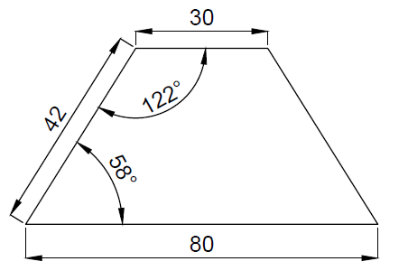
We will use the image below, and try learning all things we need to learn to be able to create something similar using AutoCAD.

We’ve learned a little how to use the coordinate system to create lines in AutoCAD. In this Session, we will forget a little about the Cartesian coordinate system.

learn-AutoCAD

It is true that using the Cartesian coordinate system we could draw lines with specified dimension, but this method is more convenient and is the one you will be making use of in the future.

Read more about how you can create lines and play with their angle

EXECUTION

To create the image above

STEP 1

Draw the line of 80 units

  1. Click on LINE
  2. Specify the first point
  3. Make sure the ORTHO mode is ON, Move your mouse rightward, type 80 and Press Enter
  4. Press Esc

STEP 2

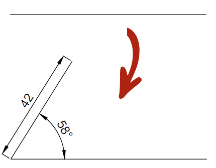
Start the second line from the first point of the 80 units line, and draw the second line with an inclination angle of 58 degrees.

learn-AutoCAD

STEP 3

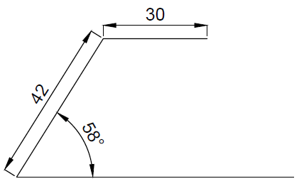
Draw the third line. It is a straight horizontal line.

learn-AutoCAD

STEP 4

All you have to do now is to create a line from the 2 open points shown on the figure in step 3.

EXERCISE

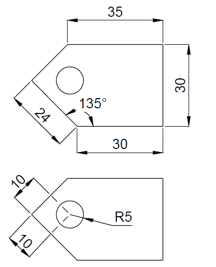
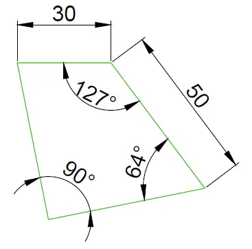
Here is a good exercise that will help you practice what we have just learned. I will suggest youlearn how to use the ROTATE command in AutoCAD before trying to do the following exercise.

Autocad-tutorial

In case of difficulties, I would like you to know that I solved this step by step few days earlier.

Categories
Articles Learning

Introduction To Auto desk AutoCAD | DAY 1

Learn AutoCAD basics: DAY 1

Welcome to Learn AutoCAD 2D basics in 21 DAYS!

Here is the first DAY. We will on this journey make use of all basic commands in AutoCAD.

The  Attempt: Handing you enough skills that you give you confidence to continue learning auto-didactically.


LEARNING AUTOCAD BASICS

Today we will start from what you need to know on Day 1. You need to have visited theseAutoCAD tutorial before diving into the following. (Jump this step and read further down, if you feel that you can handle the rest of the content without needing anything else, feel free to do so).

COORDINATE SYSTEM

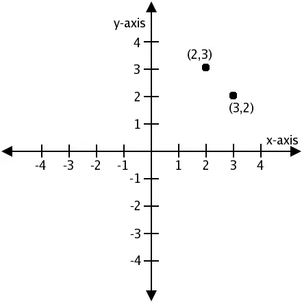
In AutoCAD, the Drawing Area is composed by a sheet in which every location has the particularity of having its own coordinate represented by x, y and z.
Learn-AutoCAD

Since we are going to be solely working in 2D in this series, we can forget about the z component of the coordinate system.

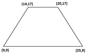
Looking at the following image, you will notice that each corner of the figure has a coordinates.
Learn-AutoCAD

Though it is true you wont be using this a lot while drawing in AutoCAD, we will spend a minute talking about it. At this point, I will suggest you disable the Dynamic input before trying the following.

We will try creating the previous image using the coordinate system and the command window. It is simple, the concept will be to use the four points to draw the quadrilateral.

To do that using autoCAD:

1. Type LINE and Press Enter
2. Type 9,9 and Press Enter
3. Type 25,9 and Press Enter
4. Type 20,17 Press Enter
5. Type 14,17 Press Enter
6. Type 9,9 And Press Enter
7. Press Esc

The first step allows to activate the LINE command. (Learn more about the LINE command)

The second step allows to specify the starting point of the line and the same goes for next steps.

The last Step allows to Cancel the LINE command.

In AutoCAD stroking Esc (ESCAPE) allows to exit a command.

At this stage, you are not using the computer mouse, and you are require to pay close attention to the command windows while drawing. As we go, we will learn more about the command windows and how to use your mouse in AutoCAD.

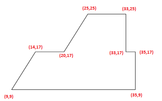
EXERCISE

Use the technique we have just learned to create the following.
learn-AutoCAD

Note you can start from any point.