Quick Tip: Object & Sub-Object Selection Sets In 3D Studio Max
In this quick tip we’ll look at an often overlooked feature of 3D Studio Max. Selection sets are a great way to keep large scenes in order by allowing you to save specific object selections, or sub-object selections. Not only will this keep you sane when working on massive scenes with hundreds or thousands of objects, but save you an enormous amount of time by essentially giving you the ability to return to a previously saved selection any time with a single click.
This post is part of a series called An Introduction To UVMapping In 3d Studio Max. An Introduction To UVMapping In 3d Studio Max Using The Unwrap UVW Modifier
In the second part we’ll take what we learned in part one and uv map an entire scene using the Unwrap UVW modifier in 3d Studio Max 2012. We’ll look at some ways to approach high-res subdivided geometry, and ways we can minimize texture stretching and distortion.
After we have UVs applied to every object, we’ll look at attaching and packing everything together in a single layout in preparation for map generation and texturing. All in all I’m hoping this tutorial will help shed some light on what is considered a major stumbling block by many beginners.
Note: click the ‘Monitor’ icon to view tutorial in full-screen HD.
Quick Tip: Assigning Hotkeys & Making Custom Menus In 3d Studio Max
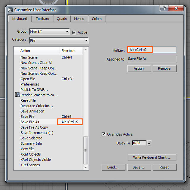
One of the most important steps in building a better, faster workflow is the addition of Hotkeys. These simple shortcut commands might only shave seconds off at a time, but in the long run those seconds can add up to hours. In this quick tip from Chandan Kumar, you’ll learn how to save time and work more efficiently by creating your own custom tool menus right inside of 3ds Max’s UI, and how to setup keyboard shortcuts for the tools you use most.
Note: click the ‘Monitor’ icon to view tutorial in full-screen HD.
We’ll look at a real world example of a computer generated car model integration into live action footage taken from helicopter. This tutorial covers the full pipeline of camera tracking, 3D scene preparation, rendering, and composing everything into a seamless shot. We’ll wrap up with the removal of the film crew and sky replacement techniques.
Quick Tip: How to Setup Units & Use the Tape Tool in 3D Studio Max
In this quick tip, Alex Martin introduces you to two features of 3D Studio Max that many new artists overlook, a correct unit setup and the ever handy tape tool. Working with a correct scene scale is extremely important, especially when it comes to multiple artists working on the same scene, or when recreating accurate lighting for a project. This quick tip will give you a few tips for setting up your units system correctly, and provide a practical example for measuring the distance between objects using the tape tool and how this applies when working with Z-Depth.
1. Unit Setup
Step 1
Whenever we create a primitive object in 3ds Max, it shows its dimensions without any proper unit by default. For example, I have created a box in the viewport and you can see there is no unit setup defined for its dimensions (Length, Width and Height). However these dimensions have some values, but we don’t know what exactly these are; meter, feet, inches, centimeters or something else?
The majority of 3ds Max users just start working this way, and this is indeed a fatal tendency. If you’re working on an architecture or industrial project, or anything which requires a correct unit setup, then you must take care of it.
Step 2
Not working with a correct unit setup can create lots of other problems. Let’s look at it through an example. Say, there are two users A and B, working in 3ds max on two different machines and both are working without setting up the correct unit order. User A has created a biped (scene 1) and user B has made a car (scene 2).
Now, after merging both projects together (scene 3), it shows the real problem. In scene 3, you can see the ratio mismatch clearly. The biped is too big for the car. This happened, because both users were working without setting up the correct unit order. If they had used the unit setup before, this problem could have been avoided.
Step 3
Now, let’s see how to work with the correct unit setup. Open 3ds Max and first of all go to the Customizemenu. Here click on the Units Setup… option.
This opens Units Setup window. Here click on the System Unit Setup button to open the System Unit Setup window. By default, it shows 1 unit = 1 inch.
This means if you draw a box in the viewport, its dimension values are in inches by default. So in this example, a Length value of 40.0 means 40 inches and so on.
Step 4
Now let’s go back to the Units Setup window. You can choose here a metric unit system also. Just turn on the Metric radio button and select any of the available units (meters, centimeters, kilometers etc). Then click on the OK button.
Now create a new Box in the viewport, and you’ll see its dimension values are in meters now.
You can change the unit system to US standard also. You can see I have changed the system unit to Feet/ Inches and now the same box’s dimension values are displaying in feet/ inches. So this is the way to get a correct measurement in 3ds Max.
Step 5
Now let’s see how we can use unit setup in a different case. I have created a biped in the viewport. The question is, how to determine the exact height of the biped? Since the biped doesn’t have any dimension values, we need to apply a trick to know the height of the biped.
There is a simple trick to set the proper height of the biped. Create a Box of the same height beside the biped. Now check the height value of the box. It shows 16 feet and 5 inches. This means the biped has the same height as well. So this is the trick to determine and setup the proper height of a biped.
2. Using the Tape Tool
Step 1
Now let’s see how to determine the proper distance between two objects in 3ds Max. I have created two objects in the viewport, and now we have to get the exact distance between the two.
To know the distance between objects, we’ll use Tape tool. Click on the Helper icon and then select theTape tool.
Step 2
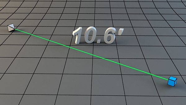
With the Tape tool selected, first click on the starting point, don’t release the mouse button and then click on the end point. The starting point of the tape tool is called the head/ tape and the end point is called the tail/ target. The connecting line in green between the head and tail represents the current distance.
Step 3
If you select the head of the Tape tool, you can see the exact length or distance between the head and tail points.
Step 4
If you turn on the Specify Length option, you’ll see the Length value gets changed and the green line of the tape tool exceeds a bit.
Step 5
You can easily set it correctly by the spinner for the Length parameter.
Step 6
Let’s see through an example, how the tape tool helps in Z-Depth channel extraction. Press the F10 key on the keyboard to open the Render Setup window. Here go to the Render Elements tab and click on Add. This opens the Render Elements sub-window. Here select Z Depth and then click on OK.
Step 7
Inside the Z Depth Element Parameters, there are two options, Z Min and Z Max. If you want the correct Z Depth value, then you must know the correct Z Min and Z Max values, which are actually the distances from the camera focus to the target objects.
Conclusion
So you can see how important the measuring tools are in 3ds Max. I hope you have enjoyed this quick tip tutorial.
Open 3ds Max. Go to Shapes > Splines > Ellipse and draw an oval shape in the front viewport.
Draw an oval shape
Step 2
With the oval shape selected, open the Rendering rollout tab. Turn on Enable In Renderer and Enable In Viewport options. Increase the Thickness value to 7.
Rendering rollout
Step 3
Right click on the oval shape and turn it into Editable Poly.
Editable Poly
Step 4
With the oval poly shape selected, click on Hierarchy panel. Enable Affect Pivot Only option and drag the pivot of the oval poly shape to the extreme right.
Don’t forget to turn off the Affect Pivot Only option after that.
Hierarchy
Step 5
Make a copy of the oval poly shape and rotate it. Both objects must not intersect each other.
Make a copy of the oval poly shape
Step 6
Make several copies of the oval shapes to form a chain link.
Make several copies
2. Creating Constraint
Step 1
With the chain selected, go to Mass FX toolbar and select Set Selected as Dynamic Rigid Body option.
Set Selected as Dynamic Rigid Body
Step 2
With the first oval poly shape from the left side selected, go to Constrains > Create Universal Constraint.
Constrains > Create Universal Constraint
Step 3
It creates a UConstraint at the pivot point of the oval poly shape.
UConstraint
Step 4
For the first oval poly object, its parent would be the next oval poly object.
Click on Parent tab and select the next oval poly object as the parent of the first oval poly object. Turn onFree radio buttons of Swing Y, Swing Z and Twist properties.
Swing Y, Swing Z and Twist properties
Step 5
You can lower the UConstraint icon size also. Put a smaller value in Icon Size.
UConstraint
Step 6
Following the same way, with the next oval poly object selected, go to Constraints > Create Universal Constraint.
Constraints > Create Universal Constraint
Step 7
It creates a UConstraint at the pivot point of the oval poly shape.
UConstraint
Step 8
For this oval poly object, its parent would be the next oval poly object. So, click on Parent tab and select the next oval poly object as the parent of the selected oval poly object. Turn on Free radio buttons of Swing Y, Swing Z and Twist properties.
Swing Y, Swing Z and Twist properties
Step 9
Following the same way, keep making constraints for each oval poly object one by one. After a couple of minutes, you will have the completed chain.
The completed chain
Step 10
Create a sphere. Put it at the end of the chain link. This will act as the wrecking ball.
Create a sphere
Step 11
Put the pivot of the sphere at the edge of the sphere as shown in the following image.
Put the pivot of the sphere at the edge
Step 12
Make this sphere as a dynamic rigid body.
Make this sphere as a dynamic rigid body
Step 13
Apply Universal Constraint to the sphere.
Universal Constraint
Step 14
For this sphere object, its parent would be the first oval poly object. Click on Parent tab and select the first oval poly object as the parent of the selected sphere object. Turn on Free radio buttons of Swing Y, Swing Z and Twist properties.
Swing Y, Swing Z and Twist properties
Step 15
Create a small low poly sphere at the extreme right end of the chain.
Create a small low poly sphere
Step 16
This time, make this sphere as a Kinematic Rigid Body.
Kinematic Rigid Body
Step 17
With the indicated oval poly object selected, apply Universal Constraint to it.
Universal Constraint
Step 18
Select the low poly sphere as the parent of it. Turn on Free radio buttons of Swing Y and Swing Z. Keep the radio button of Twist turned off.
Turn off Twist button
Step 19
With the wrecking ball sphere selected, click on Mass FX Tool icon. Inside the Mass FX Tool window, go toMulti-Object Editor tab and put the Mass value as 5.
Multi-Object Editor
Step 20
Click on Start Simulation icon. You will see a fine simulation of chained wrecking ball in the viewport.
Start Simulation
3.Installing Fracture Voronoi Script
Step 1
Go to scriptspot.com and download Fracture Voronoi script.
Fracture Voronoi
Step 2
Save the script in the 3ds Max Scripts folder.
Scripts folder
4. Fracture the Wall
Step 1
Create a box in the viewport to make a wall.
Create a box
Step 2
With the wall selected, go to Max Script > Run Script.
Max Script > Run Script
Step 3
It opens the Choose Editor file window. Select the Fracture Voronoi script and click on Open.
Step 4
It opens the Fracture Voronoi script window. Click on Pick Object button and then select the wall in the viewport.
Fracture Voronoi script window
Step 5
I have set the Nb parts as 40 since I want the wall to be broken into forty different chunks. I’ve selected theUniform color option as I want all the chunks in a same color.
Nb parts as 40
Step 6
Click on Break in 40 button. It breaks the box wall into 40 pieces.
Break in 40
Step 7
You can further break each broken piece into several more chunks. Select a broken piece and then repeat the process from Steps 2 to 6.
repeat the process from Step 2 to 6
5. Fracture Simulation
Step 1
With all wall chunks selected, make them as Dynamic Rigid Body.
Dynamic Rigid Body
Step 2
With all wall chunks selected, go to Multi-Object Editor tab and put the Mass value as 5. Turn on Start in Sleep Mode option.
Multi-Object Editor
Step 3
Click on Start Simulation button. You will see the wall shattering simulation in the viewport.
Start Simulation
Step 4
Once you are satisfied with the simulation result, click on Bake All tab to bake all simulation.
Bake All
Conclusion
Mass FX is a great dynamics tool in 3ds Max. It has replaced Reactor and has more controls over the dynamic simulation than ever.
Create A 3D Floor Plan Model From An Architectural Schematic In Blender
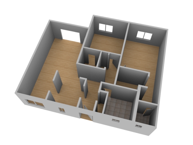
In this tutorial you’ll learn how to create a 3D floor plan model from an 2D architectural drawing. Karan Shah will show you some simple, yet effective techniques for constructing the walls, windows and doors following a basic interior schematic in Blender. With the model complete we’ll add materials and textures, and do a final render of the scene.
Step 1
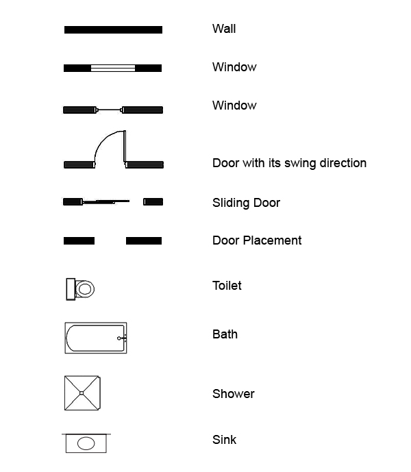
Floor Plans are simply a drawing or a diagram showing a top view of a site layout. You can see the picture to understand the meaning of some basic symbols used. More can be found
here (pdf).
Step 2
In a new file, select all objects with the ‘A’ key and press ‘Del’ to delete them. Press ‘N’ to bring up our View properties. In the Background Image Panel, add your reference image. Here I have used image courtesy ofLiamKeiranCooper Ltd who kept the picture in public domain.
Step 3
Press ‘7’ on the NumPad to get into the Top view. Here you can see the background image. The view must be set to ‘orthographic’ in order to see the image. You can toggle between the ortho and perspective views with the ‘5’ key on the Numpad. Press Shift+A and add a Plane.
Step 4
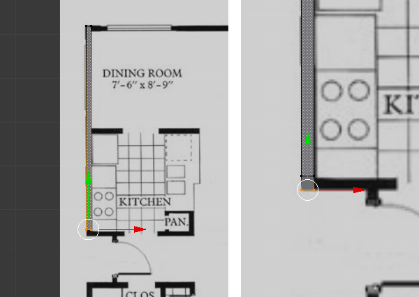
With the Plane selected, press ‘TAB’ to get into ‘Edit’ mode. Select all the vertices with the ‘A’ key, or press ‘B’ to drag select them. Press ‘G’ and move them to the top left corner. You toggle the viewport shading between solid and wireframe with ‘Z’ key. Press ‘S’ and move the mouse to scale them down to fit the width of the wall (as shown below.)
Step 5
Now we will cover all the black solid areas i.e. the walls. This will include the windows as they are part of the walls and will be added later. Any type of door whether it’s a slider or normal, is to be left out. Select the bottom two vertices (press ‘B’ to drag select or Hold ‘Shift’ and Right click for multiple select.) And move them down just before the wall turns left. Press ‘E’ and extrude the wall again until you reach the edge.
Step 6
Select the right two vertices and press ‘E’ to extrude, and match the reference.
Step 7
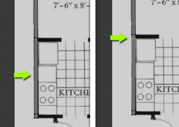
Now, in order to extrude out a face from the middle, we need to add an Edge Loop. Hover your mouse over the face, and press ‘CTRL+R’ and Left Click to confirm. Move the mouse up and down and then Left click again to confirm its position.
Step 8
Create another edge loop just below the previous one using the same method, matching the width of the wall to be extruded.
Step 9
Select the two vertices and extrude the wall.
Step 10
Create another edge loop on the corner and extrude the right edge.
Step 11
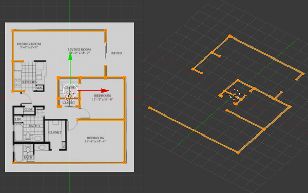
Using the techniques above (extrude and edge loop division) fill all the solid black lines of the reference image with the mesh.
Step 12
To start a new separate wall, duplicate the last edge and then start extruding it. Select the last edge and press ‘Shift+D’ to Duplicate it, and left click to confirm. Move it with the Move control widget or press ‘G’ key of the keyboard. And continue extruding the mesh along to match the reference.
Step 13
Complete the walls with the techniques you learned from above steps.
Step 14
After completing the wall, select all the vertices and then press ‘E’ to extrude them along the Z axis. Now we see that the structure is taking shape. The height should be equivalent to a door.
Step 15
Press ‘Ctrl+TAB’ and select ‘Edge’ in the mesh select mode menu. Select the top two corner edges of a door (hold shift + right click to multiple select) and press ‘F’ to make a Face between them. Do this for all doors. Refer to your image and always check from all views.
Step 16
Press ‘3’ on the Numpad to get into side view, and Press ‘Z’ to get into wireframe view so that we can see all the vertices behind are visible and can be selected. Press ‘B’ to drag select all the top vertices or edges, then Press ‘E’ to extrude them. This will reach the final height of the wall.
Step 17
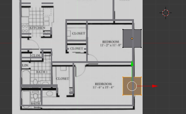
Now we will place the windows. Press ‘TAB’ to get out of the Edit mode, and in object mode, press ‘Shift+A’ and add a ‘Cube’. In the Top view, size (press ‘S’ to scale) and place it where the window is on the reference image.
In the side view, the top part of window should align to the top of door. Press ‘TAB’ to enter into the edit mode to adjust the vertices. Adjust the bottom height of the window too. The width of the cube should be such that it should be half inside and half outside. See image below.
Step 18
Select the Wall mesh with Right click, and in the Properties button window, click on ‘Object Modifiers’.
Click on ‘Add Modifiers’ and select ‘Boolean’.
Step 19
In the Boolean modifiers panel, select ‘Cube’ in the Object, and ‘Difference’ under ‘Operation’.
To see the effect – Select the cube and press ‘H’ to hide it. You will see that there is a “hole” in the wall the size and shape of the cube. Press ‘Alt+H’ to ‘Unhide’ the Cube.
Step 20
Now select the Cube (window) and in the ‘Edit’ mode, select all the vertices and press ‘Shift+D’ to make a duplicate. Place this new cube in the location of the next window.
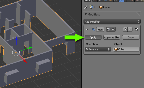
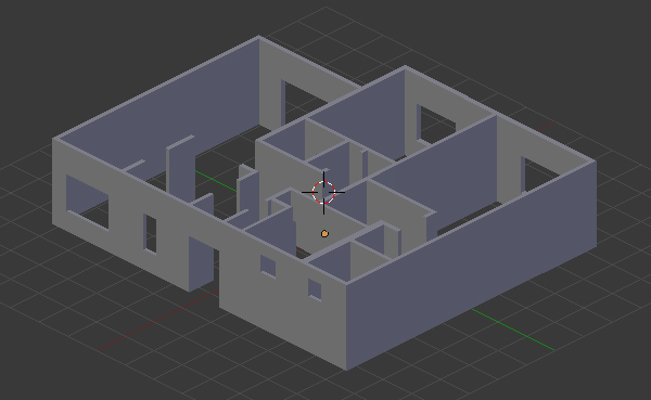
Now press ‘Tab’ to get out of ‘Edit’ mode, and select the Wall mesh and press ‘Apply’ in the ‘Boolean’ Modifier panel. The holes are now part of the geometry.
Move the Cube to see the windows.
Step 21
Similarly create all the needed windows with this Boolean modifier. Try doing them one by one, adjust the size and position of the cube according to the specific window.
Step 22
Now we will create the Floor. In ‘Object’ mode and in the Top view, press ‘Shift+A’ and add a ‘Plane’. Press ‘Tab’ to get into ‘Edit’ mode and adjust the vertices accordingly so that it covers the walls. Create Edge Loops or Extrude the edges where necessary.
Step 23
Make sure that there are no gaps between the edges of the floor and walls. Also in the Side view, move the floor down so it’s aligned with the bottom of the walls.
Step 24
To make doors, add a new’Cube’. And in ‘Edit’ mode, press / on the Numpad for Local view (this will show only the selected object.) In the Top view, Move or Scale the vertices to give it a nice shape. Refer to the image for the height and width.
In the Top view, and in ‘Edit’ mode. Move all the vertices of the door along the Y axis, so that the center point of the object (orange dot) should be at the corner (see image.) This will set the transform orientation of the object from that corner. Press ‘TAB’ to get out of edit mode and then press’R’ to Rotate and see the difference.
Step 25
While in the edit mode, add a new ‘Cylinder’. Rotate and scale it down to create the doorknob (you can add more details if you like.) Press ‘TAB’ to get out of edit mode.
Step 26
With the help of the reference image, place the doors in the correct positions (press ‘Shift+D’ to make duplicates.)
Step 27
Now we will create the window frame. Start with another new ‘Cube’, and press ‘TAB’ to enter into ‘Edit’ mode. Press the ‘Z’ key to toggle wireframe view, so that we can select the back vertices too. Press ‘3’ on the Numpad to get into side view and then extrude the faces as shown in the image to make the window frame. Press ‘TAB’ to exit out of edit mode, and press / on the numpad again to get back to the scene.
Step 28
Scale and place the window frames on the walls. Make duplicates and place them according to the image.
Step 29
Now we will add a texture to the floor. Right Click on the Floor object to select it. And in the Properties window, click on the ‘Materials’ Icon. Add a New material and name it ‘Floor’, increase the ‘Diffuse’ intensity and reduce the ‘Specular’ intensity.
Step 30
Next we will add an image to the floor. (I got mine from Here.) Click on the ‘Texture’ icon next to the Material icon, and then Click on the ‘New’ button. Select ‘Image or Movie’ for the Type and in the Image panel, click on “Open’ and browse for the image.
Step 31
You can preview the texture in the 3d View. Press ‘N’ to bring up the ‘View Properties’ and in the ‘Display’ panel, select GLSL in the ‘Shading” menu (you’ll need to add some lights in the 3d view to see the texture.) Now press ‘N’ again to hide the view properties panel.
Back to the Image Texture properties, scroll down to the Mapping Panel and increase the Size of X and Y to5 or 6 depending upon your image file.
Step 32
Now to add a separate floor to the Bathrooms, we will add a new ‘Plane’ and adjust it’s dimensions and place it just above the wooden floor so that it’s hidden.
Apply an image, just like we did on the floor (I got mine from Here.) Duplicate the Plane and adjust it’s geometry by scaling and extruding for the second bathroom.
Step 33
Select the walls and add a New material to them. Choose any color and Increase the ‘Diffuse’ intensity and set the ‘Specular’ to 0.0
Similarly assign the materials to the windows and doors. You can assign the same material to any object by selecting the material from the list.
Step 34
Now we will prepare the scene for rendering. Make sure you are Not in ‘Edit’ mode (press ‘TAB’ to toggle Edit mode on/off.) Press ‘7’ on the Numpad to get into the Top view, then press ‘Shift+A’ to add a camera.
Rotate and place it however you like. Press ‘0’ on the Numpad to get into camera view.
Step 35
Click on the ‘World’ settings and change the ‘Horizon Colour’ to white, then turn on ‘Ambient Occlusion’ and in the ‘Gather’ panel, increase the samples to 16. In the 3D view delete any lights if they exists.
Step 36
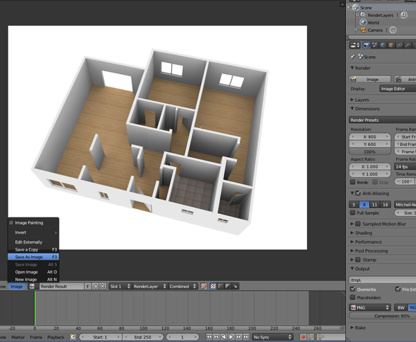
Click on the ‘Render Settings’ button in the property window, and change the Dimensions (resolution) to your desired size. Down in the ‘Output’ panel, choose the file format for your render.
Press ‘F12’ or click on the ‘Image’ button in the render panel. Press ‘F3’ or click on ‘Image > Save image as‘ to save the image.
This awesome piece of software consists of 3D modeling design, realistic animation, and renders of 3D models. There is a free 3ds max trial version to try out (See the 3ds Max download below). You can purchase the software at the link below. Also, students get to
Introduction to and history of Autodesk 3ds Max
Developed and produced by Autodesk Media and Entertainment, Autodesk 3ds Max is software for rendering 3D animation, models and imagery. It was originally called 3D Studio and was created by the Yost Group of Atari for work on the DOS platform, and development started in 1988. It later was adopted for Windows NT with 3D Studio DOS release 4 and was subsequently renamed 3D Studio MAX. 3D studio MAX, also developed by the Yost group was produced by Kinetix, which was then the media and entertainment division of Autodesk. It was the release 8 of the original 3D Studio, which was renamed Autodesk 3ds Max which was made available to the public in 2009. 3ds Max offers much functionality targeted towards ease of use and faster image and animation rendition.
Major Applications of Autodesk 3ds Max
The software is used in developing CGI as well as applications ranging from academia to game development. Each use of the software requires the use of a different set of tools available in the software and as plug-ins. 3ds Max is available free of cost for students. However profession packs are available for sale.
Major Features of Autodesk 3ds Max
Autodesk 3ds Max is primarily, although not completely, based on polygon modeling. Polygon modeling is used more extensively in game design than in other animation application as it offers a highly specific control over individual polygons that make up the model. This feature of polygon modeling also allow for greater optimization of the model.
Usually, the design process begins at the selection of a primitive model bundled with 3ds, which is then further refined as per need. The current versions have a simplified mesh editing interface and using the ‘edit poly’ modifier which moves the tools available in the primitive model, higher in the modifier stack, allowing them to be used on top of other modifications.
In the 3ds Max software various unique primitive shapes such as teapots, cones, pyramids and cubes are available which can be used as a base for model development.
Although polygons are the method of choice for model building, surfaces are easier to define using other methods. 3ds Max’s subdivision surface support allows for smoothened surfaces and with the use of tools like Soft Selection, which allows manipulation of vertex clouds into the desired shape without distortions from unwanted shapes and displaying smooth surfaces. The sculpting brush feature allows smooth surfaces to be drawn by hand, if polygons give a distorted image, although functionality is limited.
The NURBs feature of Autodesk 3ds allows smooth surface rendition by use of mathematical formulae and is of greatest use to in accurate simulation of mechanical parts. This is of greatest use in applications such as automobile design and instrument design.
3ds Max allows the use of custom lighting and shadows and highlights can also be ‘burned’ into the image rendered. These settings are mostly used for game imagery, since pre-fit values of shadows and highlights allows the game engine to process less data thereby improving game speed and performance as the model is already painted with the required modifications.
This also means that for constant lighting conditions during play, especially if motion is involved, the images do not falter and give a constant, regular image, free of improper shadows and bad graphics.
For life like character models, 3ds Max includes simulation for hair, skin, cloth and fur, all requirements for simulation of living beings. These inbuilt add-ons reduce the time required for model development and improve the detail for each frame.
It also includes rigid body dynamics which means that simulation of hard bodies such as wood or bricks, is easy to perform. This software is also equipped with features like shatter effect to recreate the dynamics of shattering rigid objects. However, soft body dynamics, which allows for the motion simulation of deformable objects, is not supported by 3ds Max, which makes simulation of such objects difficult.
A very useful feature of this software is the support for Inverse Kinematics and Forward Kinematics. Inverse Kinematics or skeleton modeling allows the user to create a model and fit it with a skeleton, which can then be animated as per the requirements of the animator. This skeleton can then be placed inside the model, making the animating the model easier.
Tools available in Autodesk 3ds Max
* MAXScript: It is a scripting language which is built into the software and can automate repetitive tasks, give varying combinations of present features and developing tools and user interfaces. MAXScript can also be used to build plug-ins for 3ds Max.
* Scene Explorer: Scene Explorer provides an orderly, hierarchical view of scene data. It allows categorical editing of data, to achieve simplicity in editing complex sets and can also manage code in .NET.
* Character Studio: Initially a plug-in character studio is a tool for help in animating virtual characters, the Character Studio allows using stock skeleton animation to quickly and easily modify characters for a project which work on the ‘biped’ skeletal system.
* General keyframing: There are two keying modes; auto key and set key which provide support for separate workflows. The keyframing controls given help in easing the animation by providing simple, but important features like cut, copy and paste.
* Constrained animation: It allows animation of objects placed inside the constraints of their shape. This tool allows the animation of objects along curves with controls provided for smoothness, velocity, alignment, banking etc. and along surfaces.
* Skinning: Using with the Physique or Skin, a fine control of movement can be achieved and can be used in the most tricky of places.
* Integration with Autodesk Vault plug-in: The Autodesk Vault is a plug-in which is shipped along with 3ds Max and is used to integrate user data and assets on to one location, thus tracking progress on projects. Also, managing work in progress is an easier task. The plug-in enables users to safely and easily design, find, reuse and share 3ds Max models for a team production effort.
Conclusion
All in all, Autodesk 3ds Max is a useful software for learning and practicing animation and developing the skills required for 3D modeling and animation purposes. Along with having a very user friendly interface, it also can be used for managing professional projects in animation. One of the best features is added plug-in functionality which increases its features by a wide margin.
Lance Evans takes you on a day-long crash course of this powerful open source 3D application.
Until the day when desktop holography becomes a reality, 3D will remain the wholly grail of the graphics world. But 3D can be a very technical craft. And each 3D program has its own idiosyncrasies, making it all a bit daunting.
I cut my 3D chops on many programs that are now long dead and forgotten. Blender is one program I’ve wanted to learn for many years. I’ve even downloaded and installed it a few times, but fell short on the follow-through to learn it. Writing this article is my personal impetus to finally get to learning it. Perhaps it can be your impetus as well. Let’s see where we can take this in just 24 hours.
Why choose Blender?
Blender has many qualities that include years of steady development, a prized commodity in either commercial or open source projects. This has netted a broad range of capabilities, beyond even its full range of 3D modeling and animation tools.
For example, Blender has video editing, camera tracking, compositing, and even game creation tools all built right in. The fact that it’s open source and completely free is also an unbeatable perk! (Though donations to the Blender Foundation are a good idea.) With all this power, Blender’s toolset is often directly compared to top programs in the 3D field costing thousands, like Mayaor 3ds Max.
Naysayers may complain it lacks centralized support, since there is no commercial publisher with a help staff. However there is ample support onlineon many sites, and even a real time IRC chat option. This means nights and weekend support too! Plus, the Blender community can be uniquely generous with its help.
The other knock is Blender’s much smaller market share, which means there are perhaps fewer companies looking to hire Blender artists. Having said that, know that this is changing and there are sites like the Blender Network that specialize in matching Blender artists with employers. And even mainstream job sites are getting more Blender savvy every day.
None of this is even an issue if you run your own shop or are just doing your own thing. Then all that matters are the final renderings. And few clients know or care about all this techno-geek talk.
Blender’s own jobs website, and it’s gaining ground on other job boards as well
My first hour with Blender: installing and learning the interface
I went up to Blender’s website , clicked on the ‘Download’ link, and chose between the installers available for Mac, Windows, Linux and even FreeBSD. (And made a small donation while there!) Installation was almost crazy-easy, and fast. Which is common for most open source programs.
Blender splash page
Once installed, I booted it up like a kid on Christmas morning. The splash page had a number of links, including one to the official Blender manual online. The manual is an excellent resource, but perhaps a bit better suited to those that already have an introduction to both 3D and Blender.
Blender’s official online manual
Upon first viewing, Blender’s interface can be overwhelming. But it isn’t as complicated as it first looks. Once you understand the logical thought process it becomes much less daunting. Logic-wise it’s rather similar to Adobe programs like Photoshop or InDesign.
Blender’s default user interface. See the text for a quick explanation of its UI
The default Blender interface is made up of four areas. (A) in the image above is called the Toolbar, a collection of the most commonly used tools. (B) is the 3D Viewport, or work window. (C) is a vertical stacking of many control/preference/properties interfaces, which again, is just like Adobe products you know. (D) is the timeline, for animation work. You might be familiar with this from programs like After Effects.
Understanding these basics makes Blender all the more approachable. Although not necessarily more useable. Before looking at any instructions, I felt compelled to muck about with the buttons, doodads and doohickeys, and hoped to find my way around. But I’ll admit that I wasn’t too successful. I began to realize that Blender wasn’t quite as intuitive – at least for me – as I had hoped.
So I started to explore what alternative ways I could go about learning it, beyond the button-poking. I quickly found out there are quite a few learning options out there.
An extreme example of multi-monitor support
Hours two-four: organizing my education
Starting my second hour with Blender, I began hunting for ways to learn it. I started out the way many of you would, by looking online for books. A quick search turned up dozens of books which included titles such as ‘Blender 3D Cookbook’ and ‘Blender Basics’ (both from PACKT Publishing), and ‘Blender for Dummies’ (John Wiley & Sons), all recently published as print and Kindle editions.
I ordered a few of these books for download. Which books best fit your learning style is up to you. As might be expected by the title, the ‘Dummies’ books take extra pains to make easing into a new subject as painless as possible, so are a good place to start. But they also tend to not go as deep as other offerings. All the books were well written and took me step by step.
And while I began learning from these books, I had to acknowledge that whether it’s our cultural evolution, or just me getting older, I found it harder to read this tech material than I used to. So I began looking for other ways to learn.
Hours four-10: video education, part one
Again, I didn’t do anything different here than most of you, I went trolling around YouTube with search phrases like ‘learn blender’, which gave a return of 157,000 videos. I’m sure most had more to do with making a good smoothie, but still, there were hundreds on Blender 3D.
An advanced subject: creating a city in Blender
Some of the most popular Blender tutorial channels included Blender for Noobswith over 27k subscribers, Blender Guru with over 153k subscribers (see the amazing architecture video!), and tutor4u with over 172k subscribers.
Pure fun: Minions in Blender!
Jacob Lewis offers a 2014 updated 10-part video series called ‘Blender Absolute Beginner Tutorial’ with about 380k subscribers. One video that is seriously worth a look is Max Coulfield’s great Blender sculpture timelapse.
‘Sculpting’ a young female head and shoulders
I spent time finding and then watching many videos, and at this point I had clocked in roughly 10 hours of working on the Blender project, across two or three days. Trying to do it all in one day would surely have exploded my tiny head.
Hours 10-15: video education, part two
After viewing YouTube tutorials for a bit, I will admit to a bias against any that begin with “Yo-yo fellas… wassup?” An experience that can leave you wanting more formally prepared material.
So I finally did something that many of you might not actually do. I contacted Ton Roosendaal, the original creator of Blender, and now the Chairman of the Blender Foundation. He was gracious and we exchanged a number of emails. At his suggestion, I got in touch with Jonathan Williamson, a co-founder and instructor at CG Cookie, an online computer graphics video education resource. CG Cookie has courseware for Blender, as well as other subjects like creative concepting and Unity game development.
CG Cookie offers online video courseware on Blender
CG Cookie offers what they call ‘Learning Flows’ for Blender, which contains 141 separate video installments. These are broken down into 9 sections, with topics like modeling, lighting, etc. The first module in the series is ‘Blender Basics’, which they make available at no cost. It contains six videos that run about a half hour total. Over the next few days I watched the intro videos, and as many of the follow-up sections as I could. All the while popping back to Blender to try things out.
Hour 15 and beyond…
I also touched base with Anja, who runs the Blender Shop on blender.org. She provided a long list of Blender learning resources, which we have reprinted at the end of the article.
So by the time I was nearing my 18th hour with all of this, I was feeling like I was in a fairly good place. By that I mean I could navigate around the interface with aplomb, I could create, modify, and texture map models (with limits on complexity), light them, and render out basic animations. In other words, I could knock out basic day-to-day 3D work. No character modeling, video editing or compositing, I’ll leave that for another day.
If this was for myself instead of an article it would have gone faster. One book and one video series would have been fine. I’m sure you’ll keep things simpler.
So what are you waiting for? Download it now, and let us know how your learning curve goes!
Resources (from Anja at Blender Shop)
A good way to learn Blender if you don’t have experience with 3D
programs is to start with Blender’s own tutorials and manual.
You can find lots of free tutorials on the internet about learning Blender.
Here are some links with lots of information:
http://wiki.blender.org/index.php/Doc:2.6/Tutorials
We have hit the last DAY of the series, and we hope we have provided you with some insight and that those will help you and give you more confidence to walk further toward your being a Pro AutoCAD user.
In this session we will rush a little bit, and learn few things you need to learn before closing.
Things we are going to be pushing forward in the following lines, are
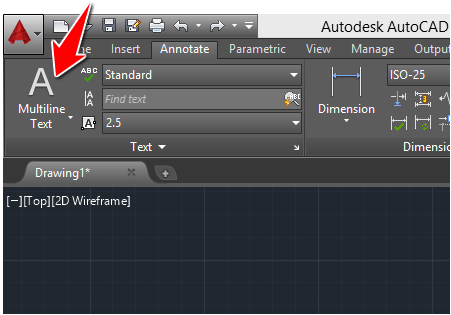
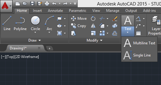
How to you write a text in AutoCAD
Working with Layers in AutoCAD
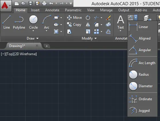
How to annotate in AutoCAD
All will be covered just from the basics point of view, but the most important will be covered.
LEARNING AUTOCAD BASICS
ANNOTATION IN AUTOCAD
Learn more about Annotation in AutoCAD
TEXT IN AUTOCAD
This can also be reached from the HOME tab
annotation
WORKING WITH LAYERS IN AUTOCAD
hey! If you have any confusion about this, Just leave a comment below. Let me know what is confusing about this, I will make it clear for you
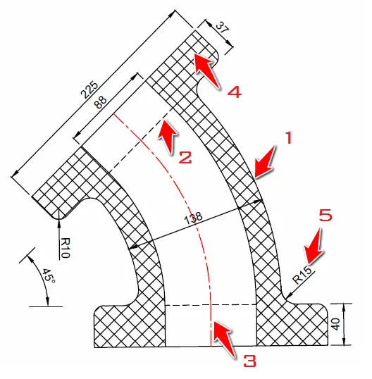
The following image will serve as an exercise.
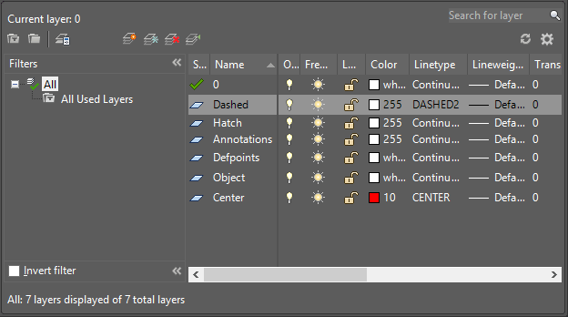
This is nothing but the image we worked on DAY 19, Now the task will be to create 5 Layers, and place each of the part of this project in its appropriate layer.
Layer 1: the Object itself
Layer 2: The Dashed lines
Layer 3: The center line
Layer 4: HATCH pattern
Layer 5: Annotations
Your layer properties manager window should look like the following.
Nothing new under the sun. Here we come again with a bushy one.
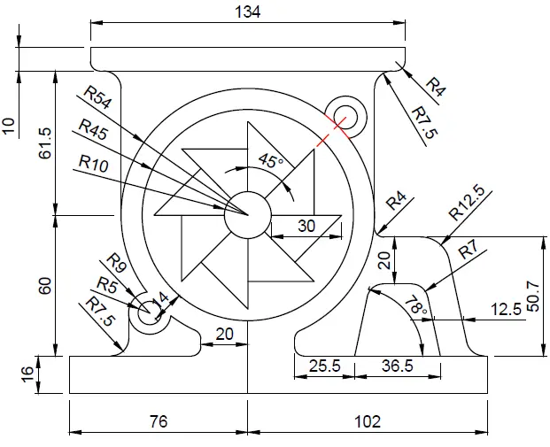
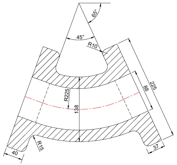
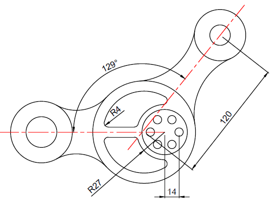
Today, you will need the ARRAY command, the FILLET command and the OFFSET command (we made an extensive use of the OFFSET command in DAY 7). There is no need to mention that you will need the LINE command, the CIRCLE command, may be the ROTATE command too.
LEARN AUTOCAD BASICS
FIGURE 1
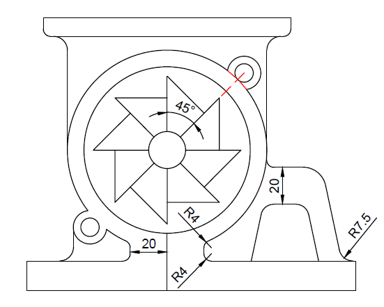
FIGURE 2
The following image provides some additional information needed to perform the exercise with success.
For the sake of exercising with the HATCH command, you can HATCH the above project at the end if you wish.
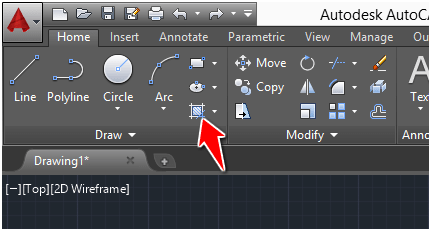
Today, we have a pretty straightforward image to replicate, and part of the task here is to use the HATCH command once the image is created.
The image below can help you locate the HATCH command.
To sum it up, they wont be lots of difficulties in this one. You need to be able to place objects however it is required in a 2D space. We tend to the end of this series, and one thing that you need to learn with these is to master the 2D space in AutoCAD. If you wish to jump into the 3D world later on, it is necessary you master how to move element in a 2D space.
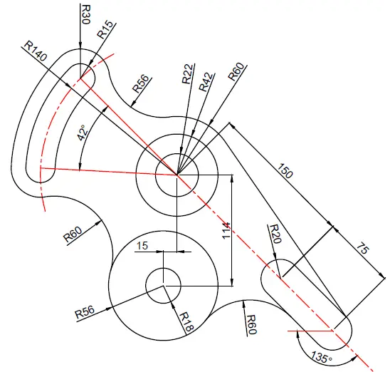
DAY 18, a lot must have happened by now. We wish you have been learning something valuable since the beginning of the series.
Here comes one of the easiest one of the series. You will agree with us that if this exercise appeared earlier that would look more difficult than it looks at this point. With all you have accomplished so far, this should be a piece of cake, just helping you retrain some of the stuff you have been learning here with the Learn AutoCAD Basics in 21 Days series.
In this session, it will be required to use the ROTATE command and the OFFSET command a lot.
LEARN AUTOCAD BASICS
FIGURE 1
hey! If you have any confusion about this, Just leave a comment below. Let me know what is confusing about this, I will make it clear for you
FIGURE 2
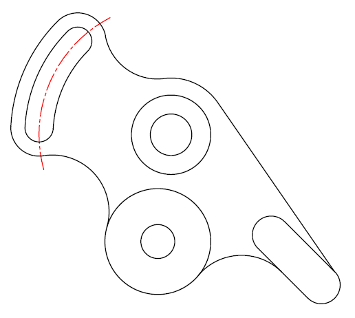
The following figure is the exercise without annotation.
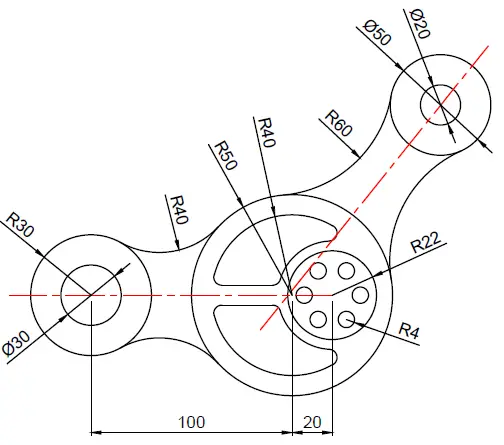
There is not much hardship in the session we are about to have. This should be a piece of cake if you have been following the series since DAY 1.
Just for the sake of knowing, here are couple of things you need to know before diving into today’s exercise:
You need to have mastered the use of MIRROR command. You can avoid using it but using it the right way to go. After creating those arcs, Use the MIRROR command to create a mirrored copy on the other side. The red lines can serve as a line of symmetry.
To create the arcs, you need to use the feature Tan Tan Radius of the CIRCLE command. If this is the first time you hear about this, it is not late to go and check it out.
LEARN AUTOCAD BASICS
FIGURE 1
FIGURE 2
To avoid the preceding image to be too bushy, we’ve split information. You can find the remaining part of the information you need in the following picture.
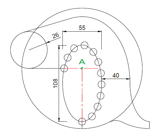
In this Learn AutoCAD basics DAY, we have learned how to grow an array on an ellipse. Today we are going to combine that skill with others to complete today’s project.
That being said, we will suggest you to master the experiment we made on DAY 12 and the use of the ARRAY command in AutoCAD before trying this one out.
LEARNING AUTOCAD BASICS
The following is the image of today’s experiment.
hey! If you have any confusion about this, Just leave a comment below. Let me know what is confusing about this, I will make it clear for you
EXECUTION
Now, we would love to provide the following images. Those will contribute to make you see clearly how you should proceed .
You can notice an ellipse of 55 x 108 on the figure below, it is what you have to use to create the array. Those small circles are equally spaced around the path of the array.
The center of the Big circle is shown on the image below and denoted by A.
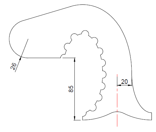
The following image gives a dimension that will be important while designing.
The red line on the last image shows a line of symmetry that will be used to get the down part of the object completed.
Note you will be required to use the OFFSET command in this exercise.
In this post, we are going to be perfecting how to handle positioning in AutoCAD.
The Object SNAP mode will be important for this session, The exercise itself is an easy one, but you need to be a bit cautious about where each of the object is placed in the project.
The use of the OFFSET command will be helpful and the ability to create a circle with the feature Tan, Tan, Radius.
LEARNING AUTOCAD BASICS
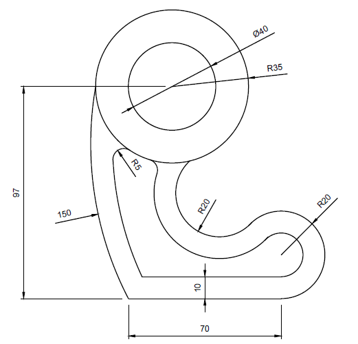
The following is the exercise we are going to be using in this session.
FIGURE 1
Additional important information are brought using the following image.
FIGURE 2
hey! If you have any confusion about this, Just leave a comment below. Let me know what is confusing about this, I will make it clear for you
EXECUTION
The following is the key image which will help complete this project.
You need to first get the above image then Trim it, and you should get the following.
What you need to do now is: Give the red part an OFFSET of 10 units, and you will end up with the following.
It is all clear now, you surely know what to do next to complete today’s task. Do not forget the two FILLET of R5 we have just below the two circles.
In this session there will be nothing difficult, except the fact that it will help you develop yoursense of analysis while using AutoCAD.
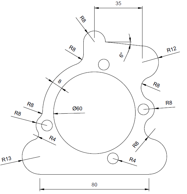
Looking at the exercise below, you should be able to, from a first look, determine all commands you need to be able to accurately replicate the object of today’s experiment.
You by now possess all you need to be able to complete the following without any problem
LEARNING AUTOCAD BASICS
FIGURE 1
FIGURE 2
hey! If you have any confusion about this, Just leave a comment below. Let me know what is confusing about this, I will make it clear for you
EXECUTION
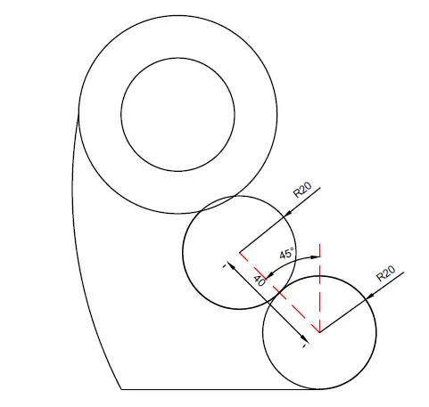
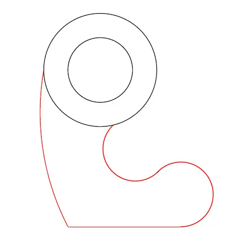
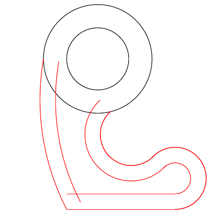
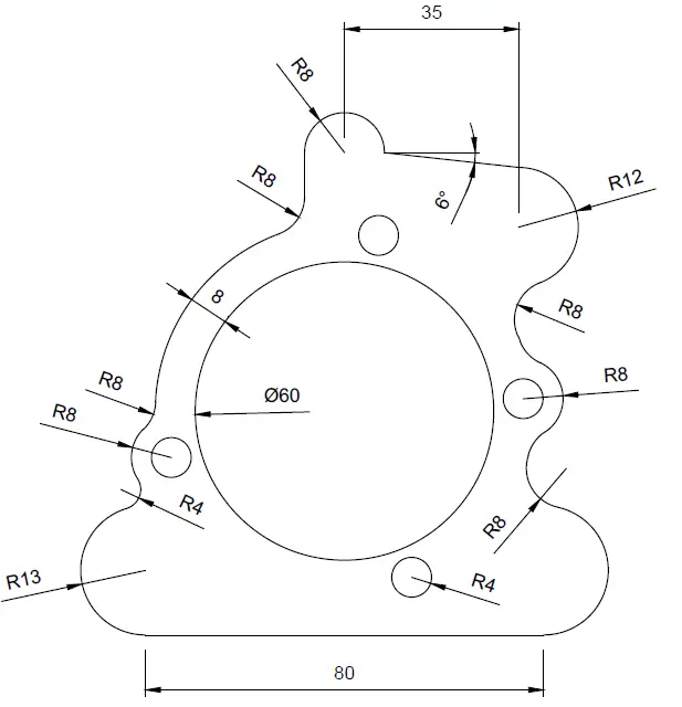
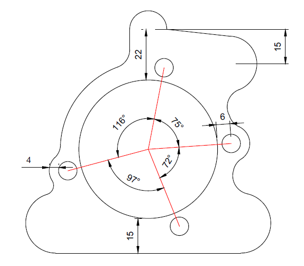
For some, figures above will not be self-explanatory enough, that is why we are bringing the following image. Pay attention to the skeleton-image used while creating the project, you will notice this is even easier that what it seemed at first.
Our suggestion will be to start from the base line (line of 80 units). All information are provided for this not to be a headache.
Feel free to drop a couple of words below in case of difficulties.
If you remember what we did in Learn AutoCAD DAY 7, you will notice that the following is quite similar to it. We had to learn how to use the OFFSET command and we have been using it throughout since sometime now. In this session, you have to use it as well.
LEARNING AUTOCAD BASICS
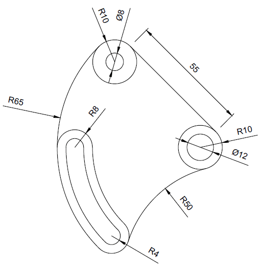
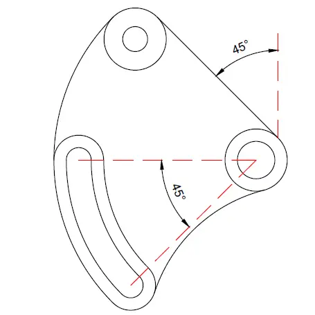
We have bent this to push you to use the ROTATE command. But it you have eyes to look at the image in a more engineering point of view, you will quickly notice that you can draw the object without inclination angle and bending it just at the end of the project, but as we indicated earlier in this series, feel free to go free-style unless stated not to. But avoid wasting time!
Take the shortest way!
FIGURE 1
hey! If you have any confusion about this, Just leave a comment below. Let me know what is confusing about this, I will make it clear for you
FIGURE 2
If you have difficulties, check how we solved the exercise on Learn AutoCAD DAY 7 and Learn AutoCAD DAY 8 that may help you. This exercise is simply the combination of those projects.



















 Cool 3D flying wing model in 3ds Max